1. REMOVAL OF MECHANICAL PARTS
AND P.C. BOARDS
CAUTION
Be careful not to remove the FFC cable forcibly, because
the FFC cable may be damaged.
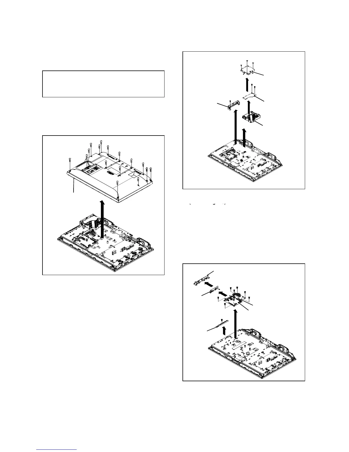
1-1: BACK CABI ASS'Y
3. Remove the Back Cabi Ass'
in the direction of arrow
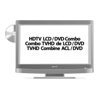
1-3: MAIN PCB /SIDE JACK PCB/OPERATION PCB
(1)
(2)
(2)
(2)
(2)
Back Cabi Ass'y
(2)
(2)
(2)
(2)
(2)
(2)
(2)
Fig. 1-2
(1)
(A)
(B)
Shield Deck
(2)
(D)
DVD MT PCB
(1)
(1)
(2)
(3)
(C)
Holder Deck B
Loader Unit
(2)
(2)
(2)
B1-1
.
2. Remove the Plate Jack in the direction of arrow
3. Remove the Shield Jack in the direction of arrow
4.
Disconnect the followin
.
5. Remove the Main PCB and Side Jack PCB in the direction
of arrow
eration PCB in the direction of arrow
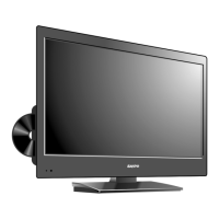
1-2: DVD MT PCB/LOADER UNIT
1. Disconnect the followin
CP2301, CP2302, CP2303, CP8501 and CP8502
.
3. Remove the Shield Deck in the direction of arrow
.
5. Remove the DVD MT PCB in the direction of arrow
6. Remove the Loader Unit in the direction of arrow
.
8. Remove the Holder Deck B in the direction of arrow
Fig. 1-3
Fig. 1-1
(A)
Plate Jack
(B)
Shield Jack
(1)
(1)
(C)
Side Jack PCB
(1)
(2)
Main PCB
Operation
(1)
(1)
(1)
(1)
(D)
B1-1