EasyManua.ls Logo

Sanyo LCD-32XH4 User Manual

Sanyo LCD-32XH4
49 pages
To Next Page IconTo Next Page
Page #1 background imageLoading...
Page #1 background image
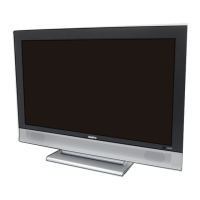
SERVICE MANUAL LCD Television
N5AV
FILE NO.
Model No. LCD-32XH4
(Argentina)
Give complete “SERVICE REF. NO.” for parts order
or servicing. It is shown on the rating label at the
cabinet back of the unit.
This T.V. receiver will not work properly in for-
eign countries where the television transmis-
sion system and power source differ from the
design specifications. Refer to the specification
table.
Service Ref. No. LCD-32XH4-00
Product Code:113011416
Original Version
Chassis Series: UH2-L
Contents
Safety Notice . . . . . . . . . . . . . . . . . . . . . . . . . . . . . . . . . 2
Specifications . . . . . . . . . . . . . . . . . . . . . . . . . . . . . . . . . 3
Chassis Block Diagrams . . . . . . . . . . . . . . . . . . . . . . 4-5
IC Block Diagrams . . . . . . . . . . . . . . . . . . . . . . . . . . 6-11
On-screen Service Menu System . . . . . . . . . . . . . 12-17
Service Adjustments. . . . . . . . . . . . . . . . . . . . . . . . . . . 18
Mechanical Disassembly . . . . . . . . . . . . . . . . . . . . 19-24
Cabinet Parts List. . . . . . . . . . . . . . . . . . . . . . . . . . . . . 25
Chassis Electrical Parts List. . . . . . . . . . . . . . . . . . 27-38
Printed Wiring Board . . . . . . . . . . . . . . . . . . . . . . . 39-45
ECO
MAIN/SUB
CHANGE
BACK
PIP
BASS
SOUND
VIDEO MODE
POWER
RECALL
DISPLAY
MUTE
AUDIO MODE
SLEEP
IMAGE
ZOOM
SURROUND
CH
CH
Question and Answer IconNeed help?

Do you have a question about the Sanyo LCD-32XH4 and is the answer not in the manual?

Sanyo LCD-32XH4 Specifications

General IconGeneral
Screen Size32 inches
Display TechnologyLCD
Aspect Ratio16:9
Brightness500 cd/m²
Response Time8 ms
InputsHDMI, Component, Composite, VGA, RF
Power Consumption120W
Resolution1366 x 768
Viewing Angle176° (Horizontal/Vertical)

Summary

Safety Notice

Safety Precautions

General safety guidelines for operating and servicing the television.

Product Safety Notice

Importance of using specified parts for safety-critical components.

Specifications

Chassis Block Diagrams

Main Signal Processing Circuit

Diagram illustrating the main signal processing flow.

Power Supply Circuit Diagram

Block diagram of the power supply section and voltage distribution.

IC Block Diagrams

Sync Separation, Analog Switch, Audio, Control ICs

Block diagrams for ICs related to sync, audio, and control functions.

Main Processor and HDMI Interface ICs

Block diagrams for the main processor (FLI8531) and HDMI interface (ANX9011L).

Power Management ICs

Block diagrams for power supply control ICs like VIPER53, L6563, L6599TR.

On-screen Service Menu System

Entering and Exiting the Service Menu

Procedures for accessing, navigating, and exiting the service menu.

Service Adjustment Data Table

List of adjustable parameters, initial values, and IC references.

Adjusting Service Data

Method for selecting and modifying specific adjustment values.

Service Adjustments

Setting Initial Data

Procedure for setting default data, especially after component replacement.

White Balance Adjustment

Steps for calibrating white balance for accurate color display.

Mechanical Disassembly

Disassembly Overview and Stand Removal

Visual guide and instructions for initial disassembly steps, including stand removal.

Cabinet, Circuit Board, and Panel Removal

Procedures for removing rear cabinet, circuit boards, and LCD panel.

Speaker Removal

Instructions for detaching the speaker units from the chassis.

Parts Lists

Cabinet Parts List

List of external cabinet components and their part numbers.

Chassis Electrical Parts List

Comprehensive list of electronic components used in the chassis.

Printed Wiring Boards

Main and Sub Board Layouts

Diagrams showing component placement on the Main and Sub circuit boards.

Power and Key Board Layouts

Diagrams illustrating component placement on the Power and Key boards.

Related product manuals