EasyManua.ls Logo

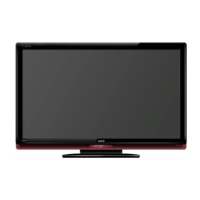
Sanyo LCD-32XH6 User Manual

Sanyo LCD-32XH6
50 pages
To Next Page IconTo Next Page
Page #1 background imageLoading...
Page #1 background image
SERVICE MANUAL
LCD Television
N6WY
FILE NO.
Model No. LCD-32XH6
(Argentina)
Give complete “SERVICE REF. NO.” for parts order
or servicing. It is shown on the rating label at the
cabinet back of the unit.
This T.V. receiver will not work properly in for-
eign countries where the television transmis-
sion system and power source differ from the
design specifications. Refer to the specification
table.
Service Ref. No. LCD-32XH6-00
Product Code:113017818
Original Version
Chassis Series: UH4-L
Contents
Safety Notice . . . . . . . . . . . . . . . . . . . . . . . . . . . . . . . . . 2
Specifications . . . . . . . . . . . . . . . . . . . . . . . . . . . . . . . . . 3
Chassis Block Diagrams . . . . . . . . . . . . . . . . . . . . . . 4-5
IC Block Diagrams . . . . . . . . . . . . . . . . . . . . . . . . . . 6-11
On-screen Service Menu System . . . . . . . . . . . . . 12-20
Service Adjustments. . . . . . . . . . . . . . . . . . . . . . . . . . . 21
Mechanical Disassembly . . . . . . . . . . . . . . . . . . . . 22-27
Cabinet Parts List. . . . . . . . . . . . . . . . . . . . . . . . . . . . . 28
Chassis Electrical Parts List. . . . . . . . . . . . . . . . . . 30-44
Printed Wiring Board . . . . . . . . . . . . . . . . . . . . . . . 45-48
Question and Answer IconNeed help?

Do you have a question about the Sanyo LCD-32XH6 and is the answer not in the manual?

Sanyo LCD-32XH6 Specifications

General IconGeneral
Screen Size32 inches
Display TechnologyLCD
Resolution1366 x 768
Aspect Ratio16:9
HDMI Ports2
Contrast Ratio1000:1
Brightness450 cd/m²
Response Time8 ms
Power Consumption120W
Input TerminalsHDMI, Component, Composite, RF

Summary

Safety Notice

Safety Precautions

General precautions to be observed for safe operation and maintenance of the television.

Product Safety Notice

Guidance on component replacement for product safety, highlighting critical components.

Specifications

Chassis Block Diagram

Main Signal Processing Circuit

Block diagram illustrating the main signal flow and components.

Power Supply IC

Block diagram detailing the power supply circuitry and its ICs.

IC Block Diagrams

IC001 QTPA3123D2--P Diagram

Pin configuration and block diagram for IC001, a TPA3123D2 audio amplifier.

IC3300 QSTV8318F---M Diagram

Pinout and schematic for IC3300, identified as STV8318.

IC750 QTMDS351PAGRP Diagram

Pin configuration for IC750, a TMDS351 HDMI interface chip.

IC7201 QCS4344-CZZ-P Diagram

Pinout for IC7201, a CS4344 audio DAC.

IC5001 QXXAVD069---P Diagram

Pin configuration for IC5001, likely a memory or I/O chip.

IC7200 QXXAVD067---M Diagram

Pin configuration for IC7200, a comprehensive multimedia processing IC.

IC003 QTPA6110A2--P Diagram

Pinout and block diagram for IC003, a TPA6110A2 headphone amplifier.

On-screen Service Menu System

How to Enter Service Mode

Step-by-step instructions to access the service menu using the TV's controls.

Side Controls Overview

Description of the physical buttons on the TV for menu navigation.

Adjusting Service Items

Guide on selecting and modifying data values within the service menu.

Exiting Service Mode

Instructions on how to safely exit the service menu after adjustments.

Service Adjustments

Setting Initial Data

Procedure for setting initial adjustment data, ensuring factory defaults are correct.

White Balance Adjustment

Detailed steps for adjusting the white balance using specific patterns and settings.

Mechanical Disassembly

Disassembly Diagram Overview

Exploded view showing the main cabinet components and their assembly.

Stand Removal

Instructions for safely removing the television stand.

Lid Back Removal

Steps for removing the rear lid or back cover of the TV.

Internal Board Removal

Procedures for removing internal boards like power and main boards.

Cabinet Back Removal

Steps for detaching the main cabinet back panel.

Key Board Removal

Instructions for removing the TV's button control board.

Speaker Removal

Steps for safely disconnecting and removing the TV speakers.

Cabinet Parts List

Chassis Electrical Parts List

Printed Wiring Board

Main Board (Part Side) Diagram

Diagram showing component placement on the main PCB (front view).

Main Board (Solder Side) Diagram

Diagram illustrating component placement on the main PCB (back view).

Power Board (Part Side) Diagram

Diagram showing component placement on the power supply PCB (front view).

Power Board (Solder Side) Diagram

Diagram illustrating component placement on the power supply PCB (back view).

Related product manuals