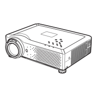
Multimedia Projector
SERVICE MANUAL
PRODUCT CODE
1 122 369 00 (KW6AC)
1 122 370 00 (LW6AC)
1 122 370 02 (LW6CC)
Original Version
REFERENCE NO. SM5110832-00
FILE NO.
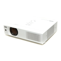
Model No. PLC-XU87
U.S.A, Canada,
Europe, U.K, Asia
Chassis No. KW6-XU8700
Match the Chassis No. on the unit's back cover with the
Chassis No. in the Service Manual.
If the Original Version Service Manual Chassis No. does
not match the unit’s, additional Service Literature is re-
quired. You must refer to “Notices” to the Original Service
Manual prior to servicing the unit.
K
!
RoHS
• This product does not contain any hazardous sub-
stances prohibited by the RoHS Directive. (You will
find “RSF” mark near the rating plate on the RoHS
compliant product.)
! WARNING
• You are requested to use RoHS compliant parts for
maintenance or repair.
• You are requested to use lead-free solder.