TD831077
VIII - 11
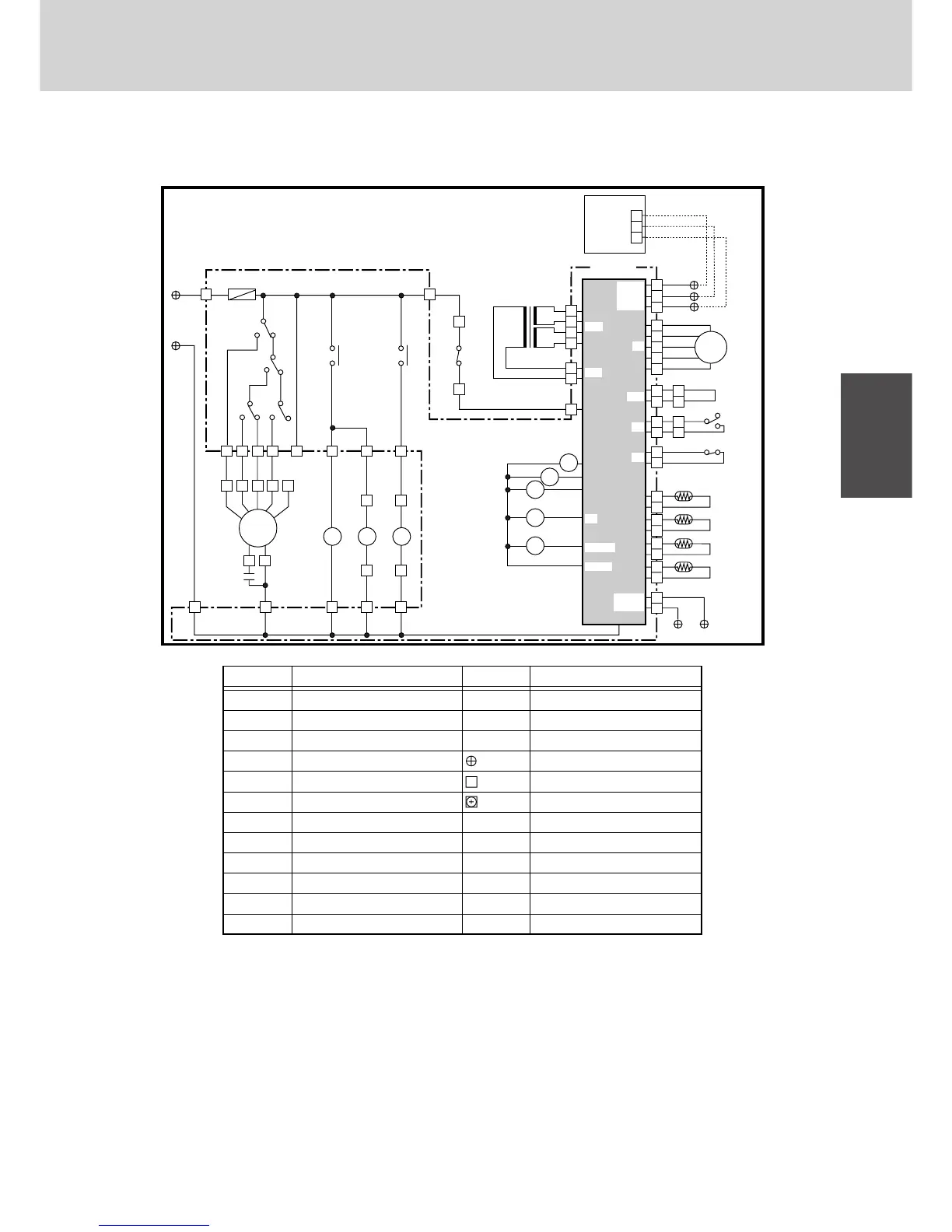
Electrical Data
8
2. Indoor Unit
(1) SPW-X(R)123GH56, SPW-X(R)183GH56, SPW-X(R)253GH56, SPW-X(R)363GH56,
SPW-X(R)483GH56
• Schematic Diagram
S 854-2-5268-470-00-3 (X)
FMI
2
1
3
1
2
1
2
1
2
1
5
6
8
7
3
1
3
1
2
1
2
3
4
5
1
2
3
4
1
TR1
T20
AC
230V
8P-
U1
8P-
U2
To Outdoor Unit
Indoor Coil
Indoor Coil
Indoor Coil
Room Thermistor
TH4
TH3
E3
TH2
E2
TH1
FS
LSW
8P-R1
CR-X253GH
Controller
8P-R2
8P-R3
E1
2
3
1
2
3
1
3
1
1
11
R
8
9
3
4
3
3
LM
NN
RC1
2X
1X
3X
RY1
RY2
2
1
3
DPH
21
143
DP
1317531
6 7543
LL L HHHHT
DP
RY2
49FI
T20
RCS
F1(5A)
1X
2X
3X 3X
8P-1(L)
8P-2(N)
RY1
DPH LM
LL L HHHR
MOV
Symbols Description
FMI
49FI
RC1
F1
LM
TR1
1X-3X
RY1-RY2
MOV
RCS
TH1
TH2
Indoor Fan Motor
Indoor Motor Thermal Protector
Running Capacitor
Fuse
Auto Louver Motor
Power Transformer
Auxiliary Relay
Auxiliary Relay
Motor Operated Valve
Remote Control Switch
Room Thermistor
Thermistor (Indoor Coil E1)
Symbols Description
TH3
TH4
CR-X253GH
DP
DPH
LSW
FS
Thermistor (Indoor Coil E2)
Thermistor (Indoor Coil E3)
Indoor Controller
Terminal Plate
Connector
Terminal
Drain Pump
Dew Proof Heater
Limit Switch
Float Switch
VCC
SG
RC12V
G
T6
PNL
LS
FS
RN2
LM
DP.DPH
DC12V
OC
SG1
SG2
 Loading...
