Do you have a question about the Sanyo VCb-3100P and is the answer not in the manual?
Details the 1/3" CCD sensor, resolution for VCB-3100P and VCB-3170P.
Highlights low smear, anti-blooming, low lag, no burning, and no geometric distortion.
Notes 100% solid state components for shock and vibration immunity.
Specifies immunity to magnetic or electrostatic fields.
Details high sensitivity with minimum illumination of 0.1 lux at F1.2.
Provides horizontal resolution figures for VCB-3100P and VCB-3170P.
Mentions the built-in high speed electronic shutter with switch settings.
Describes the new backlight compensation function for VCB-3170P.
Notes the externally adjustable flange back for mechanical focus.
Highlights low power consumption and quick start capability.
Instructions for dealing with smoke, odor, or incorrect operation.
Discourages opening or modifying the unit due to safety and damage risks.
Caution against inserting objects or liquids into the camera.
Advice to prevent damage from drops, shocks, or vibration.
Guidance on avoiding electromagnetic fields for clear imaging.
Instructions to prevent damage from humidity and dust.
Warnings about heat sources and recommended temperature range.
Methods for cleaning the camera cabinet using soft cloths.
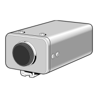
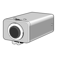
Explains the function of the POWER indicator LED.
Identifies the BNC type VIDEO OUT connector.
Refers to the connection for the AC power cord.
Identifies the BNC type VS IN connector for external synchronization.
Describes the LINE PHASE adjustment screw for image stability.
Explains the purpose of the protective lens mount cap.
Details the bracket and screw usage for camera mounting.
Identifies the 4-pin connector for DC control signal to auto-iris lenses.
Describes the internal camera settings and switches under the cover.
Advises on lens length limitations (max 7mm) to prevent camera damage.
Details the installation of a DC type auto-iris lens.
Identifies the FLANGE BACK ADJ. screw for focus adjustment.
Identifies the FLANGE BACK LOCK screw for securing adjustments.
Explains how to adjust the flange-back for correct focus.
Details the installation of a VIDEO type auto-iris lens.
Outlines the basic video signal connection to VCR or monitor.
Instructs to connect the power cord to a wall outlet.
Lists cable types (RG-59U, RG-6U, RG-11U) and max lengths.
Warns against running RG-59U through conduits/air and recommends CCTV grade.
Procedure to correct vertical image roll when using multiple cameras.
Explains how to set the AGC (Automatic Gain Control) to ON or OFF.
Details setting the electronic shutter speed from 8 speeds.
Instructions for setting the electronic iris with manual/fixed iris lenses.
Guidance for using auto-iris lenses for indoor/outdoor use.
Procedure to engage backlight compensation with auto-iris lenses.
How to adjust the LEVEL control for DC type auto-iris lenses.
Checks for power, cables, lighting, lens cap, lens type, and iris control.
Checks monitor adjustment, flange-back, focus, and lens surface cleanliness.
Advises consulting dealers for repairs and not attempting self-repair.
Details scanning system, interlace, and image device.
Lists effective picture elements and horizontal/vertical resolution.
Specifies synchronizing system and video output level/S/N ratio.
Details minimum illumination and backlight compensation functions.
Lists electronic iris and electronic shutter speeds available.
Specifies flange-back distance and gain control method.
Details environmental conditions, power supply, and consumption.
Provides weight and dimensions of the camera without mount.
| Image Sensor | 1/3" CCD |
|---|---|
| Lens Mount | C/CS Mount |
| Power | 12V DC |
| Type | Color Camera |
| Sensor | CCD |
| Horizontal Resolution | 420 TV Lines |
| Minimum Illumination | 0.7 Lux (F1.4) |
| Signal-to-Noise Ratio | 46 dB |
| Video Output | 1.0 Vp-p, 75 ohms |
| Power Supply | 12V DC |
| Operating Temperature | -10°C to +50°C |