- 5 -
26
32
33
29
28
30
31
(R)
32
31
23
24
25
25
27
27
27
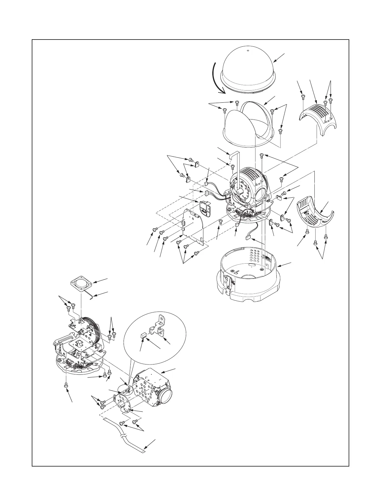
2. DISASSEMBLY
2-1. REMOVAL OF CABINET, COVER, SY-1 BOARD AND CAMERA MODULE PART
1. DEC cover
2. Four screws 2.6 x 4
3. Cover inner pan
4. Assy wire - CN492
5. Four screws 4 x 8
6. Cabinet main
7. Screw 2 x 4
8. Two screws 2 x 3
9. Cover inner tilt
10. Screw 2 x 4
11. Two screws 2 x 3
12. Cover inner tilt
13. Five screws 3 x 6
14. Five fixers
15. Assy wire - CN403 4pin
16. Assy wire - CN407 7pin
17. Assy wire - CN404 4pin
18. FPC - CN401
19. Four screws 2 x 6
20. SY-1 board
21. Two screws 2 x 6
22. Holder FPC B
23. Assy wire - CN302
24. Motor fan
25. Four screws 2 x 4
26. FPC - CN204
27. Three screws 2 x 4
28. Two screws 2 x 4
29. Two screws 2 x 6
30. Holder FPC A
31. Holder magnet
32. Magnet
A red line is the lower side (R)
33. Compl, Camera module unit
1
2
4
3
7
10
2
5
5
6
8
9
12
11
15
17
16
18
20
19
19
21
22
14
13
13
14
14
13
5
21
 Loading...