– 11 –
B
A
A
B
C
C
1
2
3
4
5
6
7
8
9
10
11
12
13
14
15
16
17
18
19
20
21
22
a
b
c
d
A
B
C
D
E
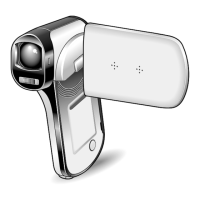
2. DISASSEMBLY
2-1. REMOVAL OF CABI LEFT, TB2 BOARD AND ST1 BOARD
1. Cover battery
2. Two screws 1.7 x 3
3. Two screws 1.7 x 4
4. Screw 1.7 x 4
5. Two screws 1.7 x 4
6. Two screws 1.7 x 4
7. Two screws 1.7 x 3
8. Screw 1.7 x 3
9. Cover joint base
10. Four screws 1.7 x 5
11. Cabi left
12. Screw 1.7 x 3.5
13. Stand
14. Cover DC
15. Spacer TB2
16. Cover IR
17. TB2 board
18. Remove the solder.
19. Connector
20. ST1 board
21. Remove the solder.
22. Spacer condenser
NOTE: Discharge a strobe capacitor
with the discharge jig (VJ8-0188) for
electric shock prevention.
When assembling,
tighten the screws order.
A → B → C → D → E
When assembling,
tighten the screws order.
a → b → c → d
234567
234567
234567
15. Spacer TB2
17. TB2 board
 Loading...