– 2 –
Table 1-1. CCD Pin Description
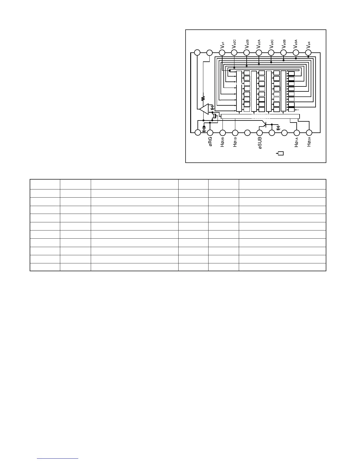
Fig. 1-1. CCD Block Diagram
1. OUTLINE OF CIRCUIT DESCRIPTION
1-1. CA1 and A PART OF CA2 CIRCUIT
DESCRIPTIONS
Around CCD block
1. IC Configuration
CA1 board
IC903 (ICX274AQ) CCD imager
IC901, IC902 (CXD3400N) V driver
CA2 board
IC911 (H driver, CDS, AGC and A/D converter)
2. IC903 (CCD imager)
[Structure]
Interline type CCD image sensor
Image size Diagonal 8.293 mm (1/1.8 type)
Pixels in total 1688 (H) x 1248 (V)
Recording pixels 1600 (H) x 1200 (V)
Pin No.
1
Symbol
2
3
4
5
6
7
8
9
10
Vø
4
Vø3A
Vø3B
Vø3C
Vø2A
Vø2B
Vø2C
GND
V
OUT
Pin Description
Vertical register transfer clock
Vertical register transfer clock
Vertical register transfer clock
Signal output
Vertical register transfer clock
Vertical register transfer clock
Vertical register transfer clock
Vertical register transfer clock
GND
Vø1
Vertical register transfer clock
Pin No.
11
Symbol
12
13
14
15
16
17
18
19
20
V
DD
øRG
Hø
2B
Hø1B
GND
øSUB
C
SUB
Hø1A
Hø2A
Pin Description
Circuit power
Reset gate clock
Horizontal register transfer clock
Horizontal register transfer clock
Horizontal register transfer clock
GND
Substrate clock
Substrate bias
Horizontal register transfer clock
V
L
Protection transistor bias
3. IC901, IC902 (V Driver) and IC911 (H Driver)
An H driver and V driver are necessary in order to generate
the clocks (vertical transfer clock, horizontal transfer clock
and electronic shutter clock) which driver the CCD.
IC901 and IC902 are V driver. In addition the XV1-XV4 sig-
nals which are output from IC102 are the vertical transfer
clocks, and the XSG signal which is output from IC102 is su-
perimposed onto XV2 and XV3 at IC901 and IC902 in order
to generate a ternary pulse. In addition, the XSUB signal which
is output from IC102 is used as the sweep pulse for the elec-
tronic shutter. A H driver is inside IC911, and H1A, H1B, H2A,
H2B and RG clock are generated at IC911.
8
1
18
19
20
2
3
4
5
6
7
13
14
15
16
17
G
B
R
G
R
G
B
G
B
G
B
G
R
G
R
G
B
V
DD
GND
C
SUB
V
L
R
G
R
G
9
10
12
11
GND
V
OUT
G
B
G
R
G
R
G
B
G
B
G
(Note)
Vertical register
Horizontal register
(Note) : Photo sensor
 Loading...