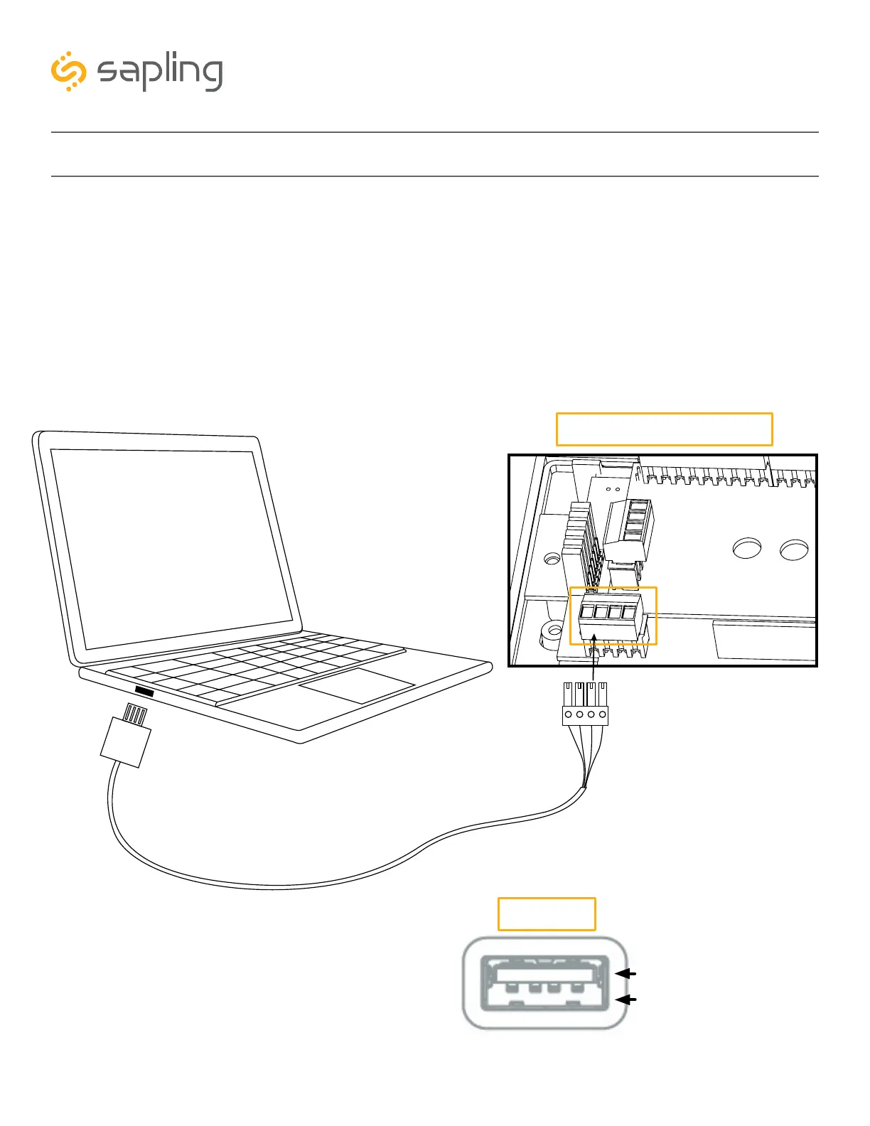
Receptacle Female Connector
for USB Programming Cable
(J7 port)
Jumper Switches
Male Power Connector
for power
43
The Sapling Company, Inc.
670 Louis Drive
Warminster, PA 18974
USA
P. (+1) 215.322.6063
F. (+1) 215.322.8498
www.sapling-inc.com
sbdconfig Installation
Step Three:
Connecting the USB Programming Cable to the clock - The USB Programming Cable has two ends.
One end is a USB-A connector and will work with any USB-A port for the purpose of connecting with a
computer or laptop. The other end has a male connector, allowing it to interface with a receptacle female
connector (J7 port) located on the clock main electrical board. Make sure that the USB-A side of the USB
Programming Cable is plugged into a computer (or laptop), and that the other side is plugged into the
digital clock main electrical board as shown in Image J below.
Port Connector
Adapter in this space
USB Programming Cable
USB-A Connector
Male Connector
Clock Main Electrical Board
USB-A Port
Image J
J7 port