42
The Sapling Company, Inc.
670 Louis Drive
Warminster, PA 18974
USA
P. (+1) 215.322.6063
F. (+1) 215.322.8498
www.sapling-inc.com
sbdconfig Installation
Step Two:
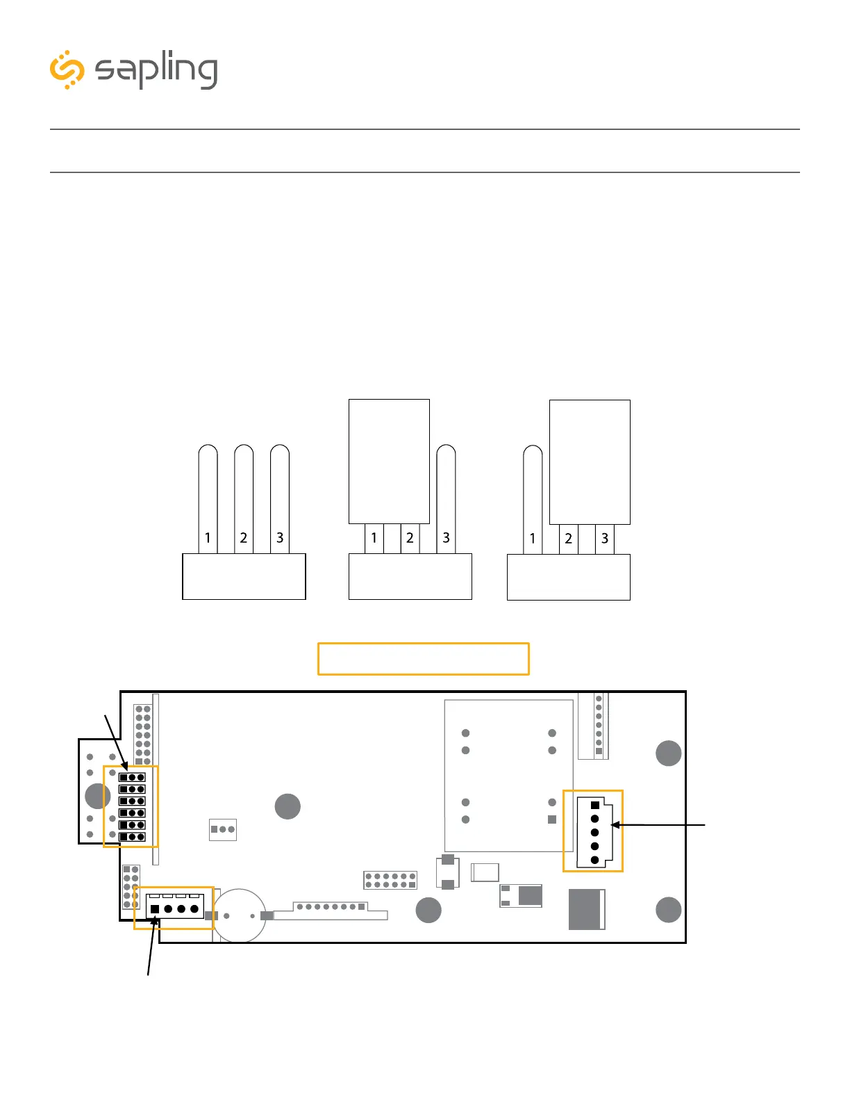
Allowing data communication from the computer to the clock – The digital clock has jumper
switches located on its main electrical board (shown in Image H). The jumper switches are located on
the left side of the electrical board and each one is numbered: JP1, JP2, JP3... JP6. In order to allow data
communication from the computer to the clock, jumper switch number 6 has to close electrical contacts
of pins 2 and 3 (other jumper switches can remain in their original location). The default position of the
jumper switches are to close electrical contact of pins 1 and 2, and the jumper switch would need to be
moved to pins 2 and 3, as shown in Image H below:
Clock Main Electrical Board
(default position- pins 1 & 2)
Image H
Image I
Jumper Switch Jumper Switch Jumper Switch
(pins 2 & 3)
Receptacle Female Connector
for USB Programming Cable
(J7 port)
Jumper Switches
Male Power Connector
for power