8 1-800-810-WIRE • www.sargentlock.com • A8203A
Copyright © 2016, Sargent Manufacturing Company, an ASSA ABLOY Group company. All rights reserved.
Reproductions in whole or in part without express written permission of Sargent Manufacturing Company is prohibited.
04/30/16
IN220 Cylindrical Lock
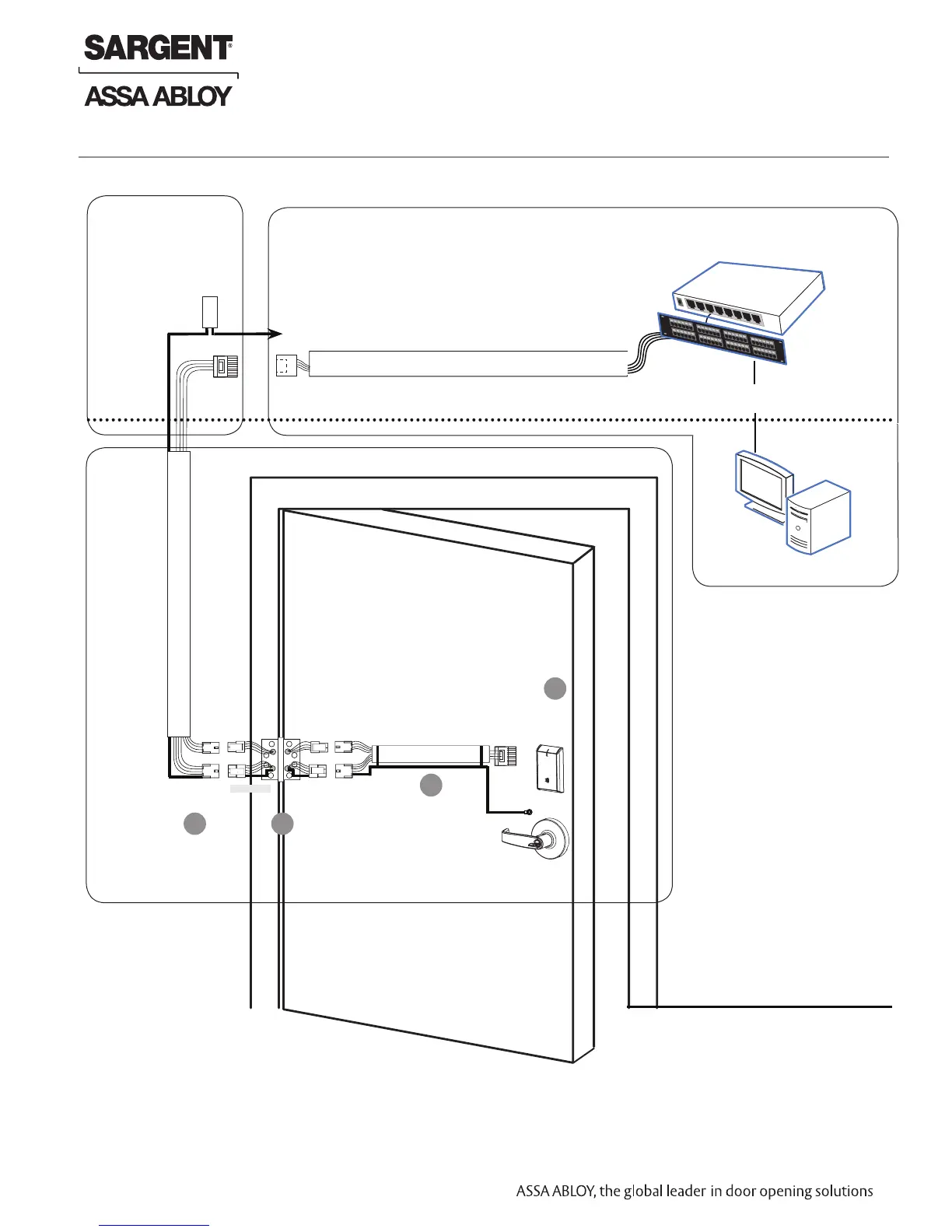
Molex-F
Molex-F
Molex-M
Cable: Cat 5e,
26 AWG stranded,
100ohm
RJ45-M
Molex-M
Cable: Cat 5e or higher
24 AWG , 100ohm
B-Splice
Crimp Connector
PoE
Lock
Ceiling
Supplied by CI
Ground
Ring Terminal
Secured to Lock
Mounting Plate
Frame-Side
Harness
Assembly
(15' length)
24AWG
Stranded
Drain
Wire for
Earth
Ground in
15' Frame
Harness
Cable
drain wire
concealed in
shrink tubing
Patch Panel
Cable: Cat 5e or higher
24 AWG
RJ45-F Jack
Approved Software
Certified Integrator (CI) supplies and terminates
the B-Splice connector and the
male RJ45 connector from harness to
end user provided facility cable
Supplied by End User
PoE Switch
PoE Switch is
Terminated to
Earth Ground
Patch Cable
Patch Panel to
PoE Switch
Wiring to TIA/EIA 568-B Standard
A
Notes:
• Connectors go on only one
way. They cannot be placed
in an incorrect position.
• Do not force and do not
offset connectors.
• Be sure they are completely
seated (flush).
• PoE power source cannot
be connected to a recep-
tacle controlled by a switch
B
C
D
To building or electrical ground
RJ45-M
Installation Wiring (Continued)
 Loading...