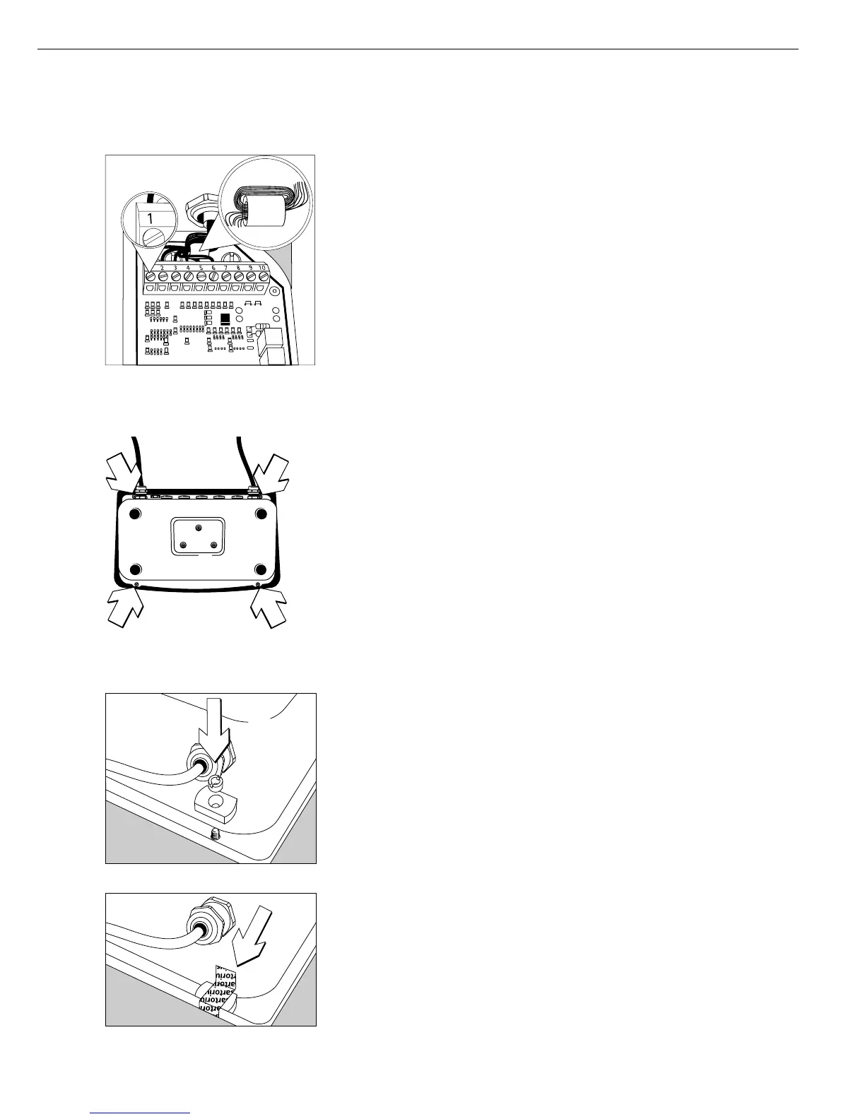
§ Connecting the cable:
– Guide the wires through the ferrite ring, wrap them around the ring once and guide them
through the ferrite ring again
– Attach the wires securely to the screw terminals
Wiring assignments:
No. Signal name Meaning
1 BR_POS Bridge supply voltage (+)
2 SENSE_POS Sense (+) for the bridge supply voltage
3 OUT_POS Measuring voltage, positive
4 OUT_NEG Measuring voltage, negative
5 SENSE_NEG Sense (-) for bridge supply voltage
6 BR_NEG Bridge supply voltage (-)
! Please refer to the service specifications or operating instructions for the load cell
or weighing platform in question for details on the assignment of wire colors to signals. Iso-
late unused wires in accordance with industry standards
! If a load receptor that uses 4-conductor technology is connected
(i.e., the cable from the load cell has only four wires), add wire straps to connect wires 1
and 2 (BR_POS and SENSE_POS) to wires 5 and 6 (SENSE_NEG and BR_NEG).
§ Close the Combics indicator:
Position the front panel on the indicator and attach it with the 4 cap nuts
Installing the Verification Adapter for Use in Legal Metrology
(on verifiable models only)
– If a verifiable weighing platform has been connected, the “Verification Adapter"
must be attached to the indicator on conclusion of platform installation.
This prevents unauthorized removal of the front panel.
§ Remove one of the cap nuts that attaches the front panel
§ Place the verification adapter on the screw and attach it with the slotted screw
§ Affix the control seal over the adapter and the screw
75