Models CIS1, CISN1 and CIS2
(IP67-protected):
Connection of open cable ends to
terminal screws inside the indicator
COM1 interface connections:
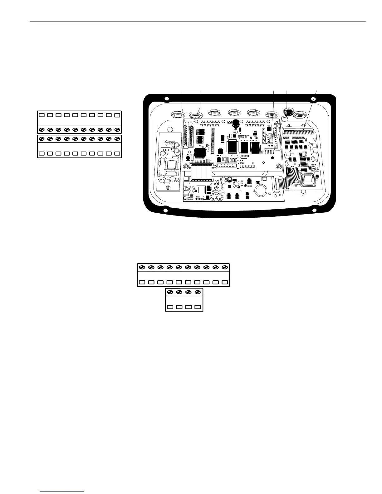
Top view
Terminal assignments
No. 1: Universal switch
No. 2: Control output “set"
No. 3: Control output “heavier"
No. 4: Control output “equal"
No. 5: Control output “lighter"
No. 6: Clear to send (CTS)
No. 7: Data output (T+D)
No. 8: Data input (R+D)
No. 9: Data terminal ready (DTR)
No. 10: Internal ground (GND)
No. 11: Supply +15 to 25 V
No. 12: Supply +15 to 25 V
No. 13: Supply ground (GND_LINE)
No. 14: Supply ground (GND_LINE)
No. 15: +12 V for printer
No. 16: Reset output
No. 17: +5 V
No. 18: +5 V
No. 19: Ground (GND)
No. 20: Ground (GND)
Models CIS1, CIS1N and CIS2: Connection
Terminals on the PCB of weighing
instrument
COM1: 11-20 1-10 UniCOM: 1- 4 1-10 (page 72)
92
Data Interfaces
Second connection: For connecting an external battery pack and a bar code scanner
1
)
(optional UNICOM interface not installed)
Terminal assignments in the
10-terminal strip
No. 1: Not connected*
No. 2: GND
No. 3: GND
No. 4: +5V Switch
No. 5: Not connected *
No. 6: Keyboard clock
No. 7: Keyboard data
No. 8: Not connected *
No. 9: Not connected *
No. 10: Not connected *
* Pin assignments depending on the UniCOM used
1
) Combics 2 only
2
) Signal from battery pack: battery drained
3
) Switch off battery pack when weighing instrument
switched off
Terminal assignments in the
4-terminal strip
No. 1: Supply, ground (GND_LINE_B)
No. 2: Supply, battery pack
No. 3: LOW_BATT
2)
No. 4: BATT_ON_OFF
3)