EasyManuals Logo

Satec Expertmeter Series User Manual

Satec Expertmeter Series
169 pages
To Next Page IconTo Next Page
To Previous Page IconTo Previous Page
Page #5 background imageLoading...
Page #5 background image
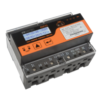
EM13x Series SMART MULTIFUNCTION METER 5
To mount the EM13X Series on flat surface:
Locate the EM13X Series on the surface to
Push up the DIN rail brackets to lock the EM13X Series on the rail.
Connecting the EM13X Series Unit
Ensure that all incoming power sources are OFF.
Check that you have the appropriate power supply.
For direct connection, connect to CT wires through the meter CT
terminals. Observe the arrow that indicates the current direction.
In case of a retrofit application or high current external SATEC CT (or
Split Core) where each external CT ends with two wires:
Connect the wire to the meter current termination
screws.
Connect the measured voltage inputs
Connect COM1 RS-485 communication port
In case of EM132/133 model with Aux. Power supply connect the Power
Supply inputs using 1.5 mm
2
/14AWG-dedicated wires.
Common Wiring Mode: EM13x and EM13x-SE 4LL3 or 4Ln3
EM13x-SE: Self Energized Meter model

Table of Contents

Other manuals for Satec Expertmeter Series

Questions and Answers:

Question and Answer IconNeed help?

Do you have a question about the Satec Expertmeter Series and is the answer not in the manual?

Satec Expertmeter Series Specifications

General IconGeneral
BrandSatec
ModelExpertmeter Series
CategoryMeasuring Instruments
LanguageEnglish

Related product manuals