PRO PM335 QuickStart www.satec-global.com
ELECTRICAL CONNECTIONS
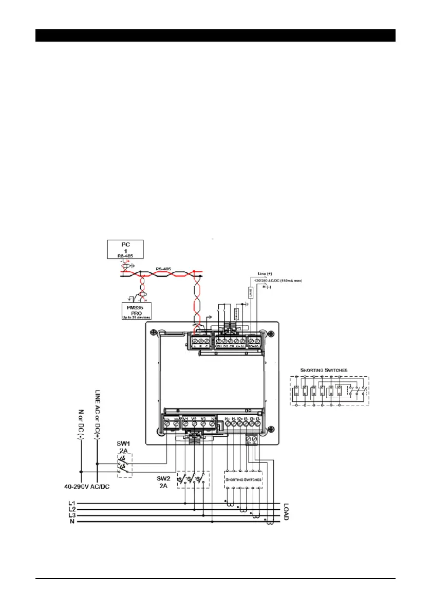
The following steps correspond with a low-voltage three phase network (figure 2):
1. Make sure all power sources are disconnected.
2. Make sure that your designated power supply corresponds with the unit's rating.
3. Connect the power supply (bottom-left of front panel) via 12 AWG wires and a
designated circuit breaker.
4. Standard external current transformers: connect the CT's (14 AWG minimum) "+" pole
to the device's I1+ current input (unit’s bottom right of rear end, as in figure 2) and the
"-" pole to the adjacent I1- current input. Repeat this for the following two phases, I2
and I3.
Verify proper polarity in your connections in accordance with the arrow printed on the
external CTs.
“HACS” CTs: connect the red/white wire to the "+" terminal and the black/orange
(colors vary according to the CT model) wire to the "-" terminal.
5. Connect the voltage measurement inputs (22-12 AWG; bottom-center of rear end).
6. Connect the com wire (26-12 AWG, shielded) to COM1 (RS485, top-left of rear-end).
7. Power-on the unit.
Figure 2: Electrical wiring