4 SATEL CA-4v1
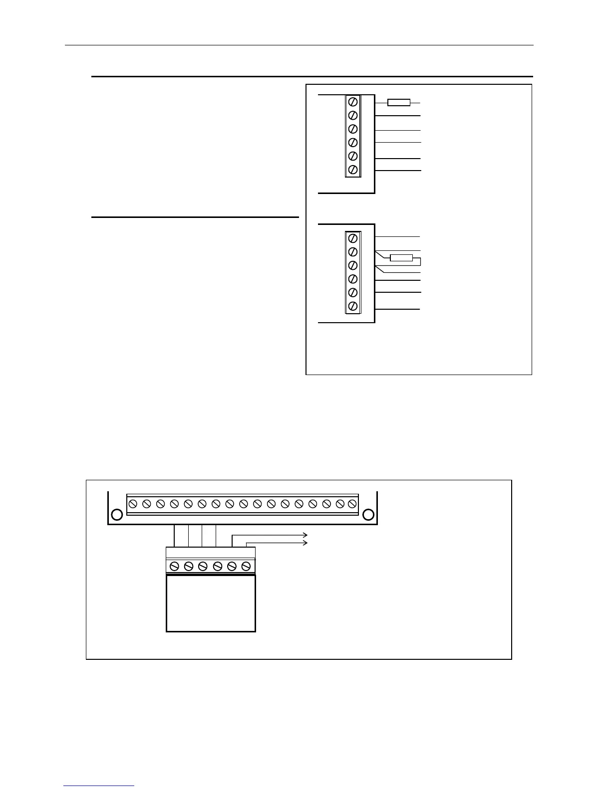
Connection of detectors
Detector wires should be connected to
proper terminals on the main board. The
way of connection 2.2kΩ EOL resistor
shown on the scheme. For powering the
detectors is intended to be used the
AUX output. TMP terminals should be
connected to a tamper circuit.
Connection of signaling devices
The signaling devices should be
connected to OUT1 and OUT2 outputs.
In the devices the 2.2kΩ resistors should
be connected in parallel to enable the
panel to control the signaling devices
wiring. If few signaling devices are
connected parallel to one output, the
resistor should be mounted in the
furthest signaling device from the control
panel.
Caution:
• The signaling devices wires control cannot replace an tampering circuit which
should be used to protect them.
The OUT1 and OUT2 outputs control the ground terminal. The +12V voltage is led
through F2 and F3 fuses to +OUT1 and +OUT2 terminals. The -OUT1 and -OUT2
terminals are cut off in inactive state, in active state (alarm signaling) they are shorted
to ground (0V).
After all the parts are carefully and properly connected the system can be power up. It is
recommended to start the alarm system only with power supply, without a battery connected.
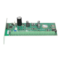
Figure 4. Connection of the signaling device
AC AC AUX +OUT1- +OUT2- COM CLK DATA +KEY Z1 COM Z2 Z3 COM Z4
Control panel CA-4v1
+ SO - + SA - SAB
Signaling device
SPL-2010
to a tamper circuit
Figure 3. Connection of the detectors