4 www.saunacore.com
Commander Controls Installation & Wiring
UNACORE .
Figure 44
Figure 33
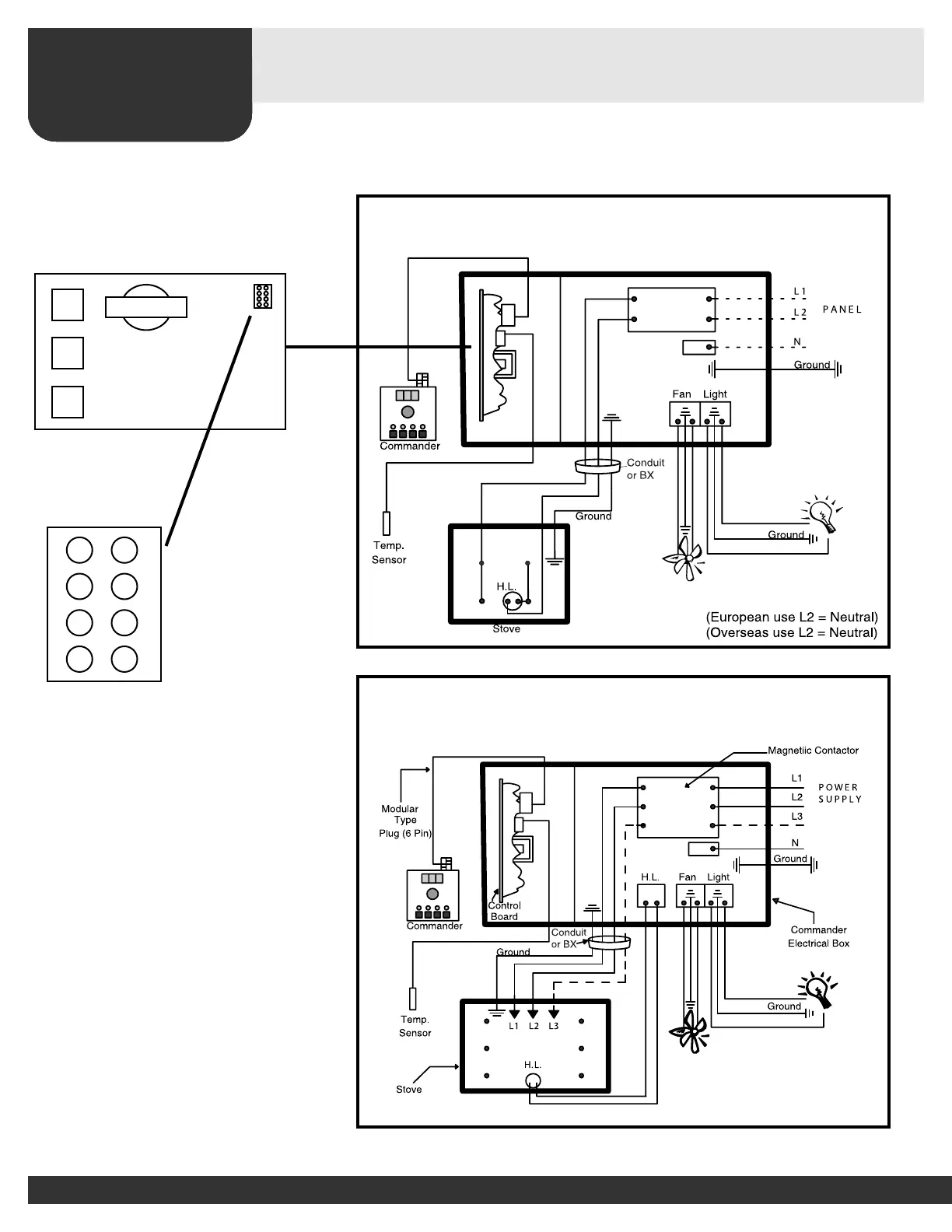
Commander Controll KW2 - KW6 Power Supply
(120v or 240v Maximum 1 Phase)
Commander Control Wiring Diagram
240v/208v 1 phase
Over 30 Amps or Any 3 phase
IMPORTANT!
Loose connections or connectors
may cause electrical shortage.
Make sure all connections and
connectors are firmly secure.
Note:
All power supply wires
from control box to stove
must be protected by
metal conduit.
4 www.saunacore.com
Commander Controls Installation & Wiring
SAU
Figure 44
Figure 33
Commander Controll KW2 - KW6 Power Supply
(120v or 240v Maximum 1 Phase)
Commander Control Wiring Diagram
240v/208v 1 phase
Over 30 Amps or Any 3 phase
IMPORTANT!
Loose connections or connectors
may cause electrical shortage.
Make sure all connections and
connectors are firmly secure.
Note:
All power supply wires
from control box to stove
must be protected by
metal conduit.
4 www.saunacore.com
Commander Controls Installation & Wiring
NACORE I\\\\\
Figure 44
Figure 33
Commander Controll KW2 - KW6 Power Supply
(120v or 240v Maximum 1 Phase)
Commander Control Wiring Diagram
240v/208v 1 phase
Over 30 Amps or Any 3 phase
IMPORTANT!
Loose connections or connectors
may cause electrical shortage.
Make sure all connections and
connectors are firmly secure.
Note:
All power supply wires
from control box to stove
must be protected by
metal conduit.
4 www.saunacore.com
Commander Controls Installation & Wiring
SAUNACORE
Figure 44
Figure 33
Commander Controll KW2 - KW6 Power Supply
(120v or 240v Maximum 1 Phase)
Commander Control Wiring Diagram
240v/208v 1 phase
Over 30 Amps or Any 3 phase
IMPORTANT!
Loose connections or connectors
may cause electrical shortage.
Make sure all connections and
connectors are firmly secure.
Note:
All power supply wires
from control box to stove
must be protected by
metal conduit.
J7 - C - PREHEAT
J6 - T - TEMP LOCK
J5 - F - CELC / FAHR
J4 - P - 30/60 MINUTES
ADD JUMPER TO CHANGE SETTINGS
CAUTION: THE MANUAL RESET LIMIT SHALL BE WIRED IN THE CIRCUIT
For supply connections, use suitable AWG wires suitable for at least
90 C (190 F).
o
o
(use copper wire only) - Ground wire must be insulated.