9
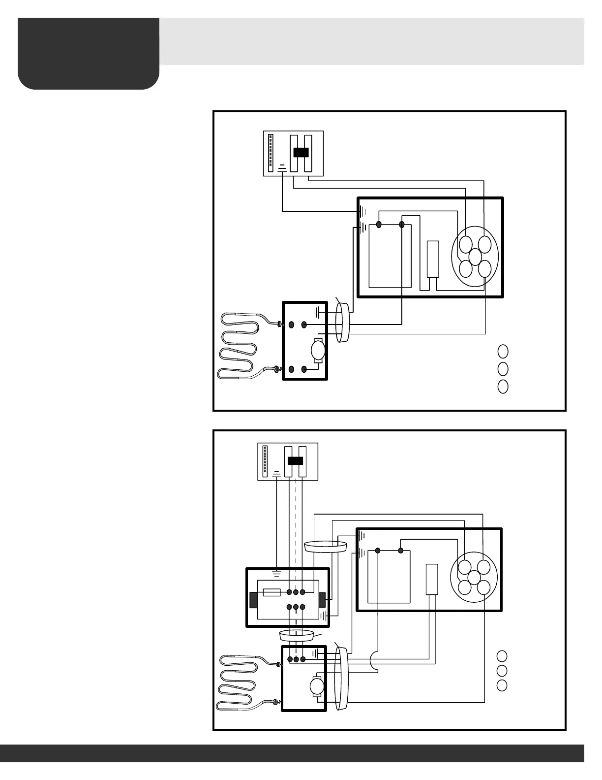
Mechanical Controls—Wiring (wall or built-in)
SAUNACORE
Figure 113
Figure 112
AB
L1
L2
T1 T2
C
Breaker Panel
MECHANICAL
CONTROL
A
B
C
Thermostat Control
240v Pilot Light
Timer
H.L.
Heater
Conduit
or BX
Coil
D
Conduit
or BX
Inline Fuse
Ground
Ground
Ground
L1 L2
L3
AB
L1
L2
T1 T2
C
L2
L1
Breaker Panel
MECHANICAL
CONTROL
A
B
C
Thermostat Control
240v Pilot Light
Timer
Ground
H.L.
Heater
Conduit
or BX
Ground
Mechanical Control
(120v/240v/1Phase 30 Amps and Under)
Mechanical Control
(240v/208v/1 Phase o
v
er 30 Am
ps and any 3 Phase)
IMPORTANT!
Loose connections or connectors
may cause electrical shortage.
Make sure all connections and
connectors are firmly secure.
Note:
All power supply wires
from control box to stove
must be protected by
metal conduit.
Inline Fuse: 5 amp 240 Volts MAX
(Offers Coil Protection)
CAUTION: THE MANUAL RESET LIMIT
SHALL BE WIRED IN THE CIRCUIT.
(Use copper wire only).
For supply connections, use suitable
AWG wires suitable for at least 90 C
(190 F).
o
o
Ground wire must be insulated.
Mechanical control must be installed outside
of the sauna room, into a 3 gang masonry
electrical box.
When a magnetic contactor is used, it also
must be installed into an appropriate metal
electrical enclosure box outside the sauna.
(For control and contactor box sizes refer to
page 7 of this manual).
European Connection
( L2 = N - "Neutral" )