Copyright © 2018 Savant Systems, LLCEntry Service with 2N Door Stations Deployment Guide
009-1540-00 | 181026
10 of 29
4. Wiring and Connections
4.1. Network
The 2N Door Stations use a standard RJ-45 port complying with
IEEE 802.3 Ethernet standards. This port also supports Power over
Ethernet (PoE) complying with IEEE 802.3af standards.
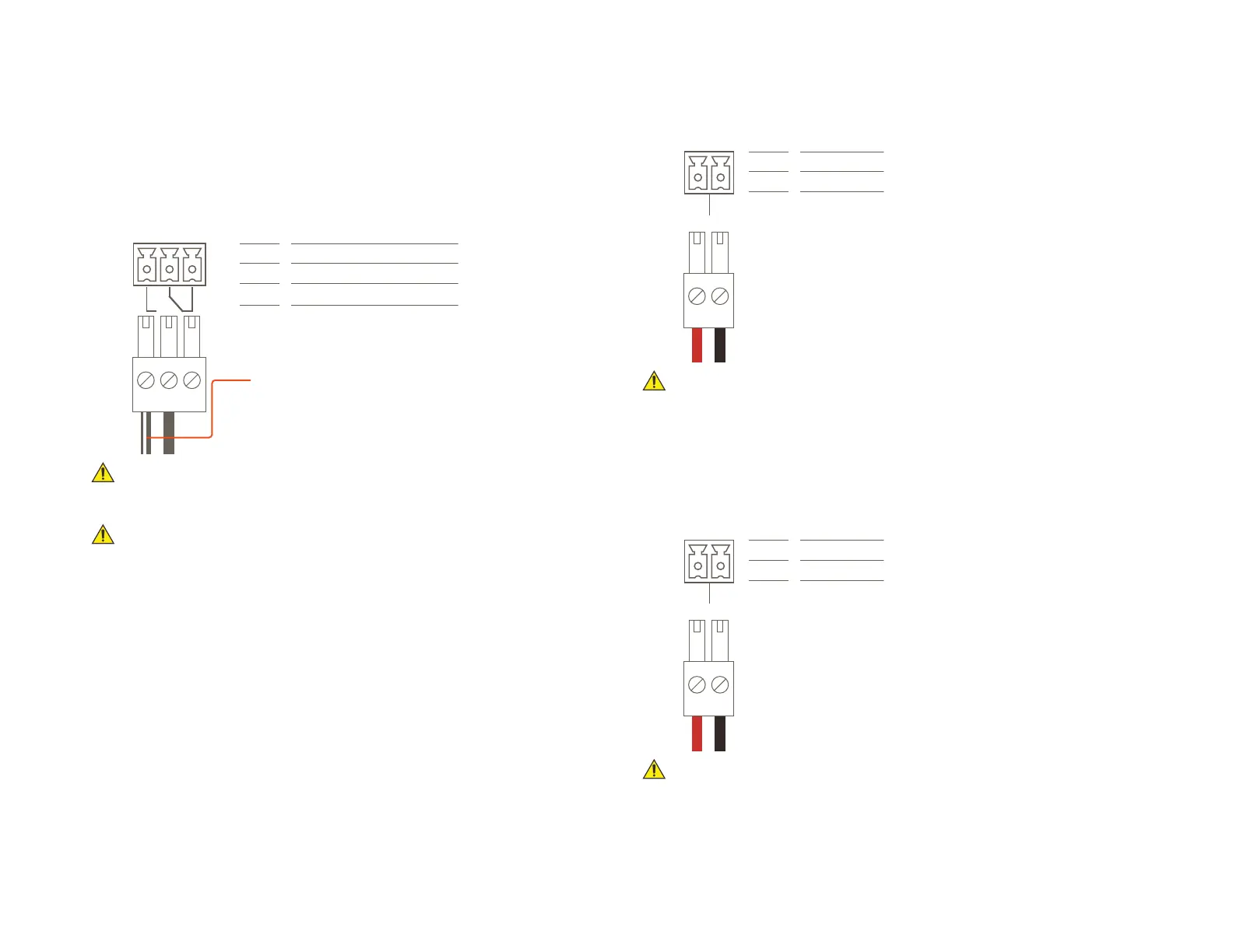
4.2. Relay
A relay port is used when a device is controlled via a normally open
(NO) or normally closed (NC) relay.
32
1
Pin 1
Pin 2
Pin 3
Normally Open (NO)
Normally Closed (NC)
Common (C)
NOTE: A white striped
wire should be
connected to the
NO or NC terminal.
IMPORTANT! The diagram above show the wiring for the Door Station
and the Heavy Gate Station. On the Single Height Door Station the
wiring order is reversed, having the NC terminal on the left side.
IMPORTANT! While Blueprint allows for control of the Relay directly, it
is recommended that they are controlled using a 2N programmed
“Switch” in the 2N’s web-GUI. This ensures the best possible user
experience.
4.3. Out1
This is an active output that provides power to a device that can be
controlled by power being supplied by an external device.
2
1
Pin 1
Pin 2
Positive
Negative
+
-
OUT1
IMPORTANT! The diagram above show the wiring for the Door Station
and the Heavy Gate Station. On the Single Height Door Station the
wiring order is reversed, having the Negative terminal on the left side.
4.4. In1
This is an active input that senses if an external device is providing
power or not. This creates a state can be tracked for use in triggers.
This control connection is on the Door Station and the Single Height
Door Station.
2
1
Pin 1
Pin 2
Positive
Negative
+
-
IN1
IMPORTANT! The diagram above show the wiring for the Door Station.
On the Single Height Door Station the wiring order is reversed, having
the Negative terminal on the left side.
 Loading...