Hardware manual PCD1.M2220-C15 │ Document 27-640 – Version ENG03 │ 2020-03-25
Saia-Burgess Controls AG Communication interfaces
5
5-5
On-board | RS-485 (Port #0+1)
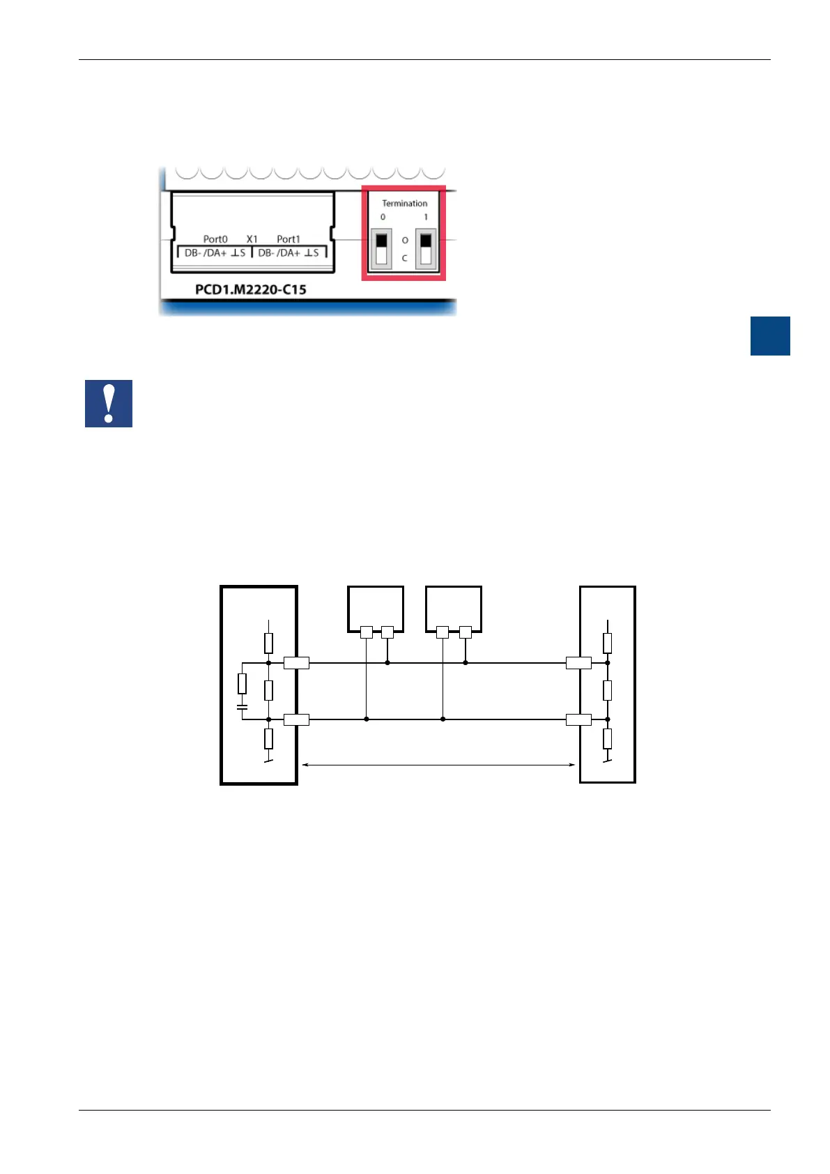
“Termination0”and“Termination1”switch
(switchingtheRS-485terminatingresistoronoro)
RS-485 terminating resistor switch for Port0 and Port1
With both of the switches mentioned above to the right of terminal block X1,
the terminating resistors at both external stations of both S-Bus wires that
are isolated from each other are switched on and o.
- The switch must be set to “C” (closed) at both external stations of the RS-485 line.
- The switch must be in position “O” (open) for all other stations.
SchematicdiagramofaRS-485buswithterminatingresistances.
+3V3
/RX - /TX
n n
DB-
/DA+
/n/n
RX - TX
+3V3
150E
1800E
1n
DB-
/DA+
DB-
Pull up
560 Ohm
Termination
Segment length max. 1200 m
max. 32 stations
Bus RS 485
First station Middle stations End station
Pull down
3300 Ohm
More details can be found in “26-740_DE_Handbuch_RS485-Komponenten Net-
zwerke”.


 To Next Page