4
2. INSTALLATION
The MTH100 DI must be installed on a 35 mm DIN rail and in watertight enclosure.
Installation should comply with current local standards.
Any installation or work of any nature should be carried out by a certified professional.
The equipment must feature a ground-fault breaker.
The installation must be properly grounded.
The power supply should be switched off prior to any work being carried out on the equipment
(including cleaning).
Initial START-UP : HEATER OPERATING TEST.
Programme the control module (minimum 1 step),or start it up in “MAXI” PRESET MODE
(see page 18) after adjusting setpoint Tc to a value greater than the ambient temperature
(see page 9).
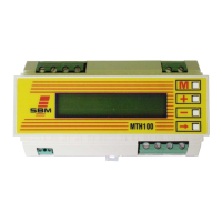
INSTALLATION ON DIN RAIL IN ELECTRICAL CASING
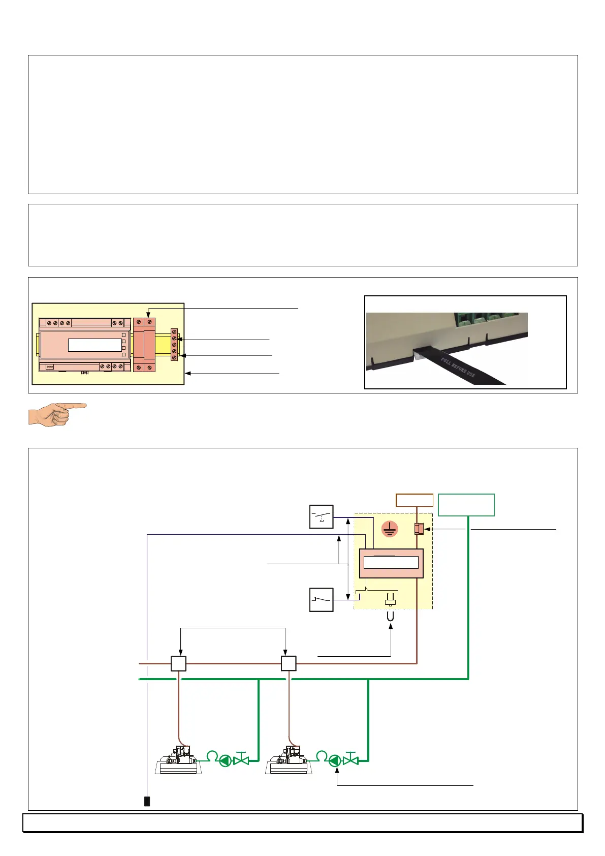
DIAGRAM OF SINGLE SPEED MODEL
WITH RI HEATERS OR RADIANT TUBES
Gas
Temperature
sensor
RI heaters
(or radiant tubes)
Ground-fault breaker
RP3
230V AC
External NO push-button
as optional extra
(not supplied by SBM)
External safety
or
Bridge (included in
the sensor packet)
Sensor cable
MTH100 DI
MTH100 DI
Valve + Regulator + Metallic hose
Ground-fault breaker
Pull the protective strip off the battery.
DIN rail 35 mm
Ground terminal
Watertight enclosure
A safeguard battery keeps date and hour in case of voltage interruption.
For keeping lifetime of battery, let the module under voltage during non-
heating season.