Installation instructions 4 - 5
Doc.nr : 6611-018
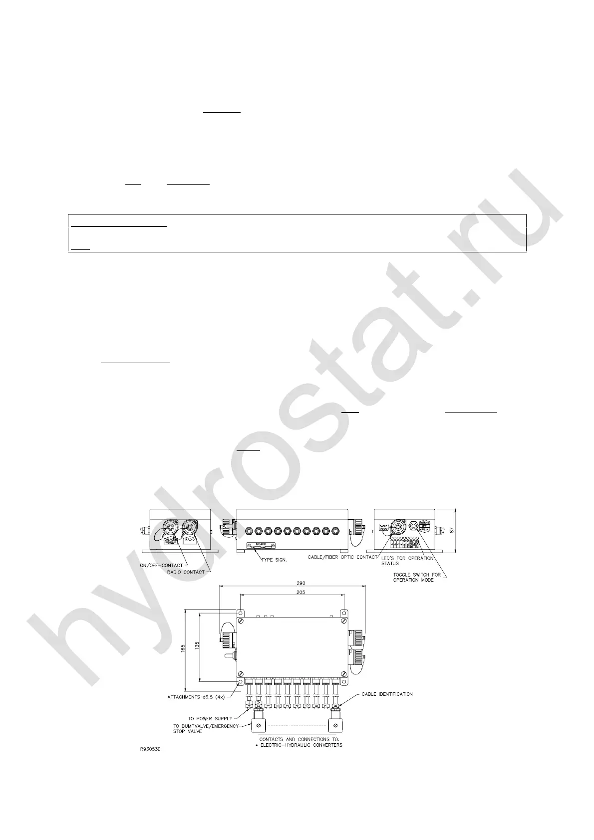
2. Select a suitable location for the electronicbox on the vehicle / crane.
• The contact for the cable control cable, switches for
0$18$/5(027( and LEDs
for operational status must be located where they are easy to see and reach. Check that
the electronicbox cable contacts ( FDEOHFRQWURO
212))DQG UDGLRUHFHLYHUER[
FRQQHFWLRQFRQWDFWV ) are located so as to be protected from external damage.
• If the electronicbox is to be mounted in any other manner, the connections and contacts
must not face upwards ! This is to hinder long-term accumulations of water, damp and
corrosive salt in the cables, connections and contacts.
127(0DULQHFUDQHV The casing of the electronicbox is grounded and connected to supply voltage earth. In
those special cases where a galvanically isolated earth is required ( for ex. marine use ), the radio receiver’s box
must be mounted on rubber stand-offs/bushes to obtain a galvanically isolated earth.
3. Connect the electronicbox valve contacts, as per the schematic in which each valve group
and function can be seen. A valve gasket is mounted under each valve contact and to
prevent future operational disturbances, a weatherproof grease / silicon should be applied
between the valve contact and the manoeuvre valve.
• The valve contacts for the electro-hydraulic slide controller are marked and numbered
, , up to .
7KHFRQWUROXQLWVOHIWPDQRHXYUHOHYHU YDOYHFRQWDFW
7KHFRQWUROXQLWVULJKWPDQRHXYUHOHYHU YDOYHFRQWDFW
• The valve contacts for the dump valve are marked '9 ( Max. RXWSXWGULYHPD[$PS
7KHIXQFWLRQLVDXWRPDWLFDOO\FXWRIILIORDGHGE\PRUHWKDQ$PSLHWKHRXWSXWLVQRWGDPDJHG ).
• All cable and valve contacts must remain in place even for valve contacts which are not
used. Unused valve contacts should be carefully sealed with grease and electrical tape
( to keep damp out which could cause operational disturbances / alarms ).

 Loading...