28
2019-03-06 / V1.0
Installation
Contactors CT/CU Series – Installation and Maintenance Instructions
Installation with busbars:
Contactor types CT/CU 1115/11, 1130/11, 1215/11,
1230/11
Depending on the contactor type, see Fig. 37 to Fig. 38.
Busbars for the above listed contactor
types must be installed on the top side
side of the heat sink using screws long
enough for that purpose.
Schaltbau strongly re commends Schnorr-
Washers (or similar) to secure the screws.
The use of press nuts at the busbars will
simplify installation and maintenance.
X
Place the busbars (1) on the top side of the heat
sink (2).
X
Screw the busbars (1) on the main terminals (2) on
the top side side of the heat sink using appropriate
screws and washers.
- Schaltbau strongly re commends Schnorr-Wash-
ers (or similar) to secure the screws.
X
Tighten the screws with the rated torque.
- for terminal screws M10: max. 20 Nm
- for terminal screws M12: max. 30 Nm
(refer also to the label on the upper module).
If the busbars are rather inexible it is rec-
ommended to use an additional angled
bar (3). This compensates mechanical tol-
erances between the mounting platform
for the lower module and the busbars in
all 3 axes.
1
1
2
2
1
3
3
1
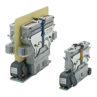
Fig. 37: CT/CU 1115/11, 1130/11: Install busbars
1
2
1
2
1
3
1
3
Fig. 38: CT/CU 1215/11, 1230/11: Install busbars
 Loading...