Domotique embarquée
Embedded home automation
P. 6
Domotique embarquée
Embedded home automation
Installation instructions
• This device must be placed in a place protecting it from any risk of water splashing. Install in a ventilated location
• Do not install on supports that are sensitive to heat, such as carpet or PVC ooring, etc.
• The product must be installed away from heat and humidity
Meaning of the LEDs:
- LED off: the circuit is inactive.
- LED on: the circuit is active.
!
WARNING: Connection/disconnection with power on
Do not perform connection or disconnection with power on.
INPUT / POWER SUPPLY
Type of connection
Cross section
Clip 8mm + connector 2-way
de 6 à 16 mm²
OUTPUT
Type of connection
Cross section
2 x spring connectors 6-way
6 mm²
CAN BUS 2 x CAN connectors type 6-way Micro-Fit
LIN BUS 1 x LIN connector type 4-way Micro-t
CODAGE With DIP SWITCH
PROTECTION TO BE PROVIDED ON THE SUPPLY LINE
Protection rating
Protection location
Fuse or circuit breaker 50A maximum
Accessible and identied for the user
Connection
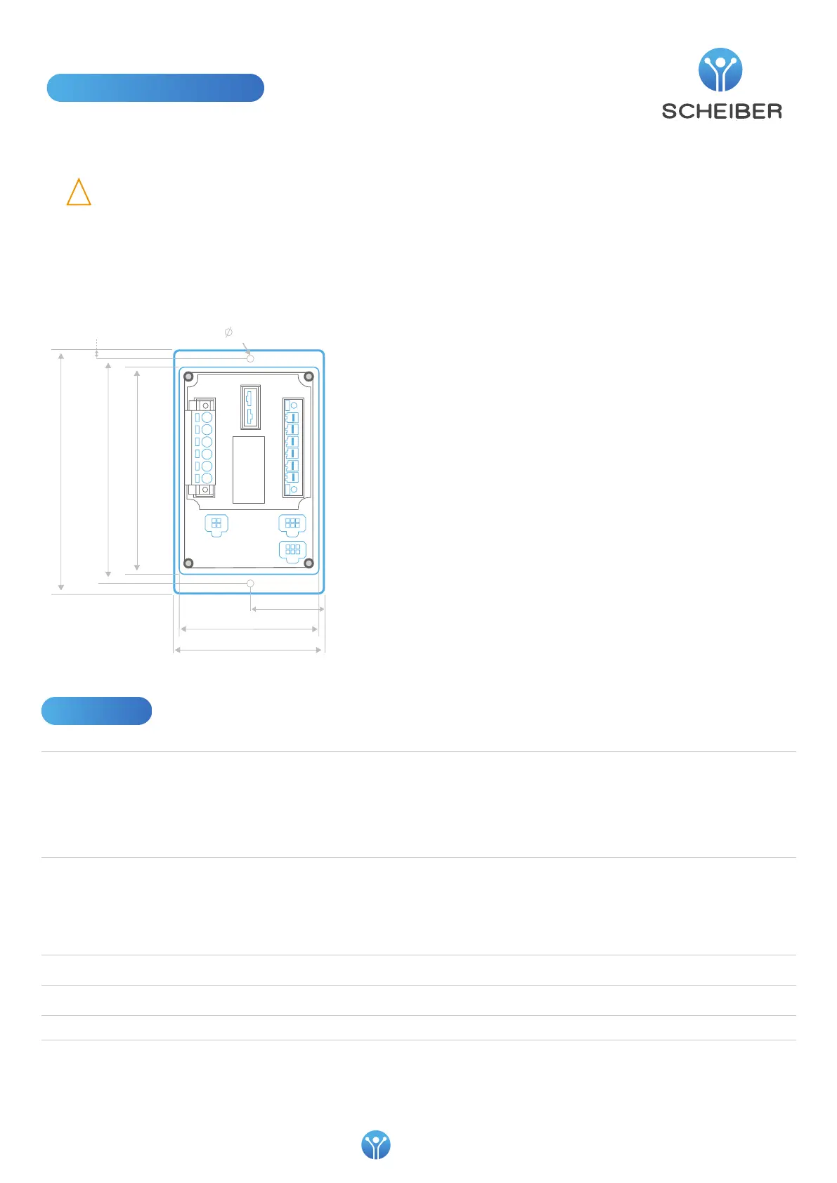
Mounting:
95
84,50
150
138
125,50
3,20
Installation cutouts:
84,50 x 125,50 mm
Mounting distance :
45 x 138 mm
Mounting distance of the 2 screws support :
138 mm
Visible thickness after mounting :
14,3 mm
Back clearance zone for connection :
80 mm (behind the product)
47,5
6