21GB
www.scheppach.com / service@scheppach.com / +(49)-08223-4002-99 / +(49)-08223-4002-58
7. Before putting the machine into
operation
Before you connect the equipment to the mains
supply make sure that the data on the rating plate
are identical to the mains data.
Always pull the power plug before making
adjustments to the equipment.
Pull the power plug before doing any maintenance
or assembly work on the equipment.
• The machine must be set up so that it stands rmly,
i.e. it must be securely screwed to a work bench or
similar.
• All covers and safety devices have to be properly t-
ted before the equipment is switched on.
• The grinding and polishing wheel must rotat freely.
• Check that the voltage on the rating plate is the
same as your supply voltage before you connect the
equi ment to the power supply.
7.1 Fitting the spark re ector (Fig. 2-4 / Item 3)
Fit the spark re ector (3) to the double wheel grinder
using the adjusting screw (10).
7.2 Adjusting the spark re ector (Fig. 5 / Item 3)
• Adjust the spark deector (3) using the adjusting
screw (10) so that the distance between the dry
grinding wheel (5) and the spark deector (3) is as
small as possible and certainly does not exceed 2
mm.
• Adjust the spark deector (3) periodically to com-
pensate for wear on the wheel.
7.3 Fitting the workpiece supports (Fig. 6 / Item 8)
Secure the workpiece supports (8) to the double wheel
grinder using the star screw (7).
7.4 Adjusting the workpiece supports (Fig. 7 / Item 8)
• Adjust the workpiece supports (8) using the star
screws (7) so that the distance between the dry
grinding wheel (5) and the workpiece support (8) is
as small as possible and certainly does not exceed
2 mm. • Adjust the workpiece supports (8) periodi-
cally to compensate for wear on the dry grinding
wheel (5).
7.5. Changing the wheels (Fig. 8-9)
• Remove the 3 screws (A) holding the side section
of the safety hood (B) and remove the safety hood.
Slacken the nut (D) (Important: The grinding wheel
on the left is fastened with a lefthanded thread and
the grinding wheel on the right with a right-handed
thread) by holding the nut of the grinding wheel
mount on the opposite side.
• Then remove the ange (C) and replace the grind-
ing wheel (5). To assemble, proceed in the reverse
order. The grinding wheel is mounted with the help
of a rag. Mount the ange (C) and the nut (D) on
the shaft and hold steady with the help of a rag
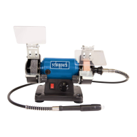
6. TECHNICAL DATA
HG34
Mains voltage
230 V ~ 50 Hz
Power rating
120 W
Idle speed n
0
0-9900 min-
1
Grinding wheel diameter
75 mm
Polishing wheel
diameter
75 mm
Wheel thickness
20 mm
Wheel hole diameter
10 mm
Max. peripheral speed
50 m/s
Protection class
II
Weight
3.1 kg
Sound and vibration
Sound and vibration values were measured in
accordance with EN 61029.
L
pA
sound pressure level ..................... 75,8 dB(A)
K
pA
uncertainty .............................................3 dB
L
WA
sound power level ....................... 88,7 dB(A)
K
WA
uncertainty .............................................3 dB
Wear ear-muffs.
The impact of noise can cause damage to hearing.
Total vibration values (vector sum of three directions)
determined in accordance with EN 61029.
Vibration emission value a
h
≤ 2.5 m/s
2
K uncertainty = 1.5 m/s
2
Warning!
The speci ed vibration value was established in ac-
cordance with a standardized testing method. It may
change according to how the electric equipment is
used and may exceed the speci ed value in excep-
tional circumstances.
The specied vibration value can be used to compare
the equipment with other electric powertools.
The specied vibration value can be used for initial
assessment of a harmful effect.
Keep the noise emissions and vibrations to a
minimum.
• Only use appliances which are in perfect working-
order.
• Service and clean the appliance regularly.
• Adapt your working style to suit the appliance.
• Do not overload the appliance.
• Have the appliance serviced whenever necessary.
• Switch the appliance off when it is not in use.
• Wear protective gloves.
 Loading...