international 25
Changing the knives (Fig. 11)
• Put the main switch of the machine to OFF position.
• Pull the power supply plug from the socket.
• Block the cutter block guard in the lifted position.
• Release and remove the four knife clamping screws.
• Lift the knives and knife support from the cutter
block.
• Remove the chips and any resin from the cutter block
• and knife support.
• Place new knives into the cutter block and fix them with
the rectangle slots in both screw heads. (With these two
screws, height-adjustment of the knife is done.)
• Place the knife support onto the knife.
• Slightly tighten the four clamping bolts.
• Repeat these actions for the second knife.
• Then adjust the planer/thicknesser knives exactly with
the output table. Use a ruler that you put onto the out-
put table.
• By the two set screws, the knife can be adjusted for
height.
• By turning the cutter block and using the ruler, you can
see the height adjustment.
• The knife is exactly set, when the ruler is moved by the
knives not higher than 3 mm.
• After a successful knife setting, all clamping screws
must be tightened (8.4 N/m).
Please mind:
• Sharp planer/thicknesser knives guarantee a clean plan-
ing surface and put less stress on the motor.
• After three grinding actions, a maximum material re-
moval of 3 x 0.05 mm may not be exceeded.
• The planer/thicknesser blades used on this machine are
not suitable for rebating and dovetailing.
• Finally lower the cutter block guard again onto the ta-
ble. Cover the cutter block and block it with the star
grip screw.
Installation
• Make sure there is sufficient space for handling the
work piece over the whole length without the opera-
tor (or another person) having to stand in line with the
work piece.
• Using bolts, washers and hexagon nuts (not supplied
with the machine), the planer/thicknesser can be bolted
to a work bench.
• The planing machine must be bolted onto a firm, level
surface.
• The machine may not tilt, and the table must be
aligned.
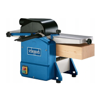
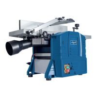
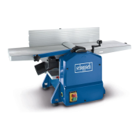
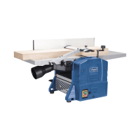
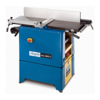
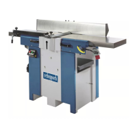
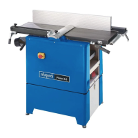
Machine setting up and functions
The electric planer/thicknesser is transportable. It is pow-
ered by a single-phase motor and is double insulated. It
has been designed for planing wood, and it features a ra-
tional construction, easy operation, and high efficiency.
Remplacement des fers de rabot (Fig. 11)
• Mettre l’interrupteur à la position «Arrêt».
• Débrancher la prise d’alimentation.
• Bloquer la protection de l’arbre de rabotage dans sa
position la plus haute.
• Relâcher et enlever les 4 vis de serrage de lame.
• Enlever la lame et le support de l’arbre.
• Enlever copeaux et résine de l’arbre et du support.
• Mettre la nouvelle lame dans l’arbre et la fixer par les
fentes dans les 2 têtes de vis. (Ces 2 vis servent à ré-
gler en hauteur la lame.)
• Mettre le support de lame sur la lame.
• Serrer légèrement les 4 vis de serrage.
• Répéter la procédure pour la deuxième lame.
• Ensuite, régler précisement la hauteur des lames en re-
lation à la table d’enlèvement, en utilisant une règle.
• La hauteur des lames est réglées par les deux vis de
réglage.
• Vérifier la hauteur des lames en tournant l’arbre, tout
en maintenant la règle sur place.
• La lame a la position correcte si la règle est avancée
par les lames pas plus de 3 mm.
• Ensuite, reserrer toutes les vis fermément (8,4 N/m).
Faire attention:
• Ne travaillez qu’avec des lames bien affûtées. Elles dé-
chargent le moteur et garantissent une surface lisse.
• Après avoir affûté les lames trois fois, l’enlèvement de
matériel ne doit pas excéder 3 x 0,05 mm.
• Les lames usées sur cette machine ne sont pas appro-
priées à entailler en queue d’aronde.
• Finalement abaisser la protection de l’arbre de rabo-
tage sur la table, couvrir l’arbre et le serrer avec la vis
poignée-étoile.
Installation
• Vérifier qu’il y ait de la place suffisante pour guider le
bois sur toute sa longueur, sans qu’une personne doit
se trouver dans une ligne avec la pièce à travailler.
• La rabo dégau peut être fixée sur un établi à l’aide de
boulons, rondelles et écrous hexagonaux (non livrés).
• La rabo dégau doit être vissée fermément à une surface
solide et lisse.
• La machine ne doit pas basculer, et les tables doivent
s’aligner.
Construction et fonctions de la machine
La rabo-dégau peut être transportée. Elle est actionnée
par un moteur monophasé et a une isolation double. Elle
a été conçue pour travailler le bois. Sa construction est
rationnelle et de haute efficacité, et elle est facilement
maniable.