2. System Description
2.1. Hardware
The hardware elements of the Wireless CDR system consist of the Wireless Sensor (with
battery pack); Antenna / Receiver and USB Interface units (known collectively as the
Base Station), a compatible PC workstation, and interconnecting cables.
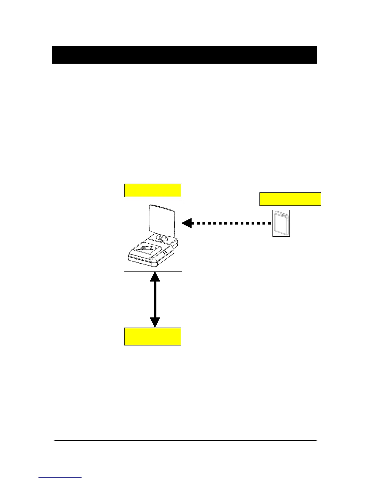
The following block diagram shows the functional relationships between modules and
devices within the CDR Wireless system. The Antenna / Receiver unit can be located
remotely from the USB Interface unit via Category 5 cable (RJ-45 connectors); however,
in the following illustration, they are shown in their default ("docked") configuration.
Wireless Sensor
2.4 GHz RF Link
(wireless)
Base Station
Antenna / Receiver
USB Interface
USB Link
(wired)
Figure 1. CDR Wireless System
PC
W
rk
i
n
4 B1051301 Rev. - (DRAFT) CDR Wireless User Guide