2.1.2. Base Station Antenna / Receiver
The Base Station is composed of the Antenna / Receiver and USB Interface. The Antenna
/ Receiver receives the radio frequency status and image data signals from the Wireless
Sensor, demodulates the signals and transfers the information to the USB Interface. When
the Antenna / Receiver is receiving data, the LED located near the base of the Antenna
illuminates.
The Antenna / Receiver can be positioned separately from the USB Interface to enhance
signal reception. Nominally, the Antenna / Receiver should be within 6 feet (1.8 meters)
of the Wireless Sensor and facing the patient for best results. The Antenna can be pivoted
forward-and-back and rotated from left-to-right to achieve optimum reception.
The Antenna / Receiver and USB Interface are shipped connected directly to each other
("docked"). Two screws are used to secure the units. Remote mounting of the Antenna /
Receiver from the USB Interface is optional, and may be prompted by a number of
factors (including physical layout of the office and / or RF reception). The base of the
Antenna contains molded areas to allow for wall- and ceiling-mounted options.
When the Antenna / Receiver is mounted remotely, the two screws securing the Antenna
/ Receiver to the USB Interface are removed allowing the two units to be unplugged from
each other. A standard computer network modular Category 5 cable with RJ-45
connectors is then used to connect the Antenna / Receiver to the USB Interface.
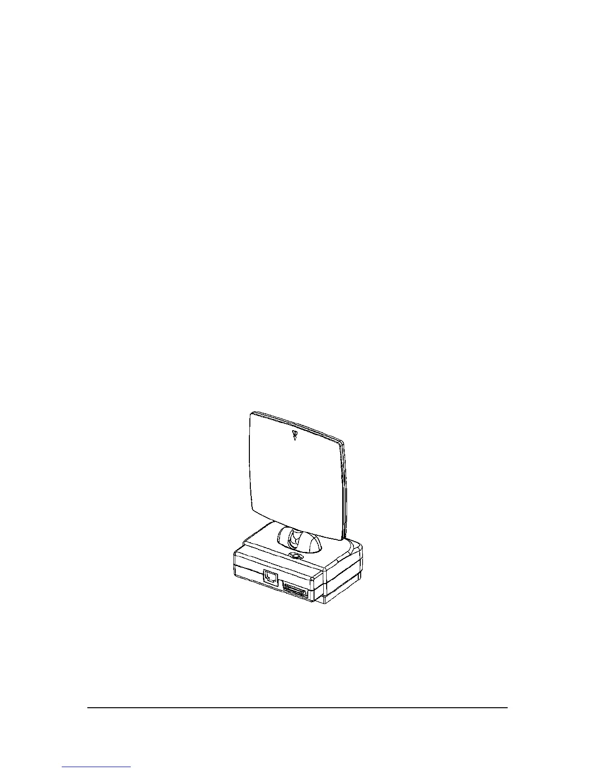
Figure 3. Antenna / Receiver
6 B1051301 Rev. - (DRAFT) CDR Wireless User Guide