17
Installation Instructions
ELBOWS AND 90˚ INSPECTION ELBOWS
For offset information on standard elbows, please refer to p.14
Please note that 90° Inspection bends may be incorporated into a connecting flue pipe
arrangement on all fuels, please refer to National Annex of BS EN 15287-1 for specific guidance
re use on solid fuel applications, the diagrams on p.7-8 give guidance.
In cases of top mounted stoves, a minimum vertical height of 600mm from the appliance must
be respected prior to any change of direction in the flue pipe.
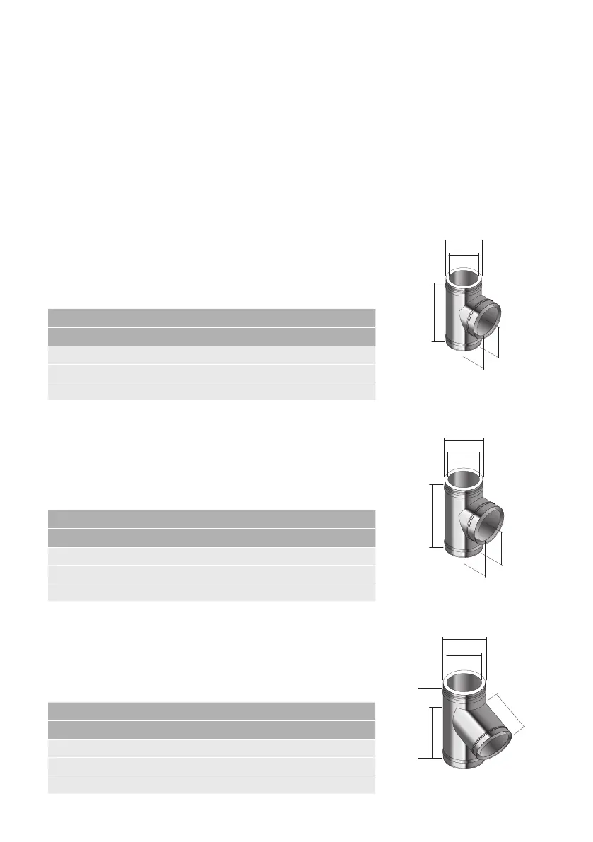
90˚ TEE
This component may be used to connect from a connecting
flue pipe to the vertical system chimney at 90° or the branch
may be used to locate a draft stabiliser. It is installed as per a
standard pipe section.
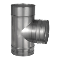
93˚ TEE
This component must be used in place of a 90° tee to connect
from a connecting flue pipe to the vertical System Chimney
on condensing systems to ensure that condensate can drain
down through the system to a drain point. This component is
installed as per a standard pipe section.
135˚ TEE
This component may be used in combination with a 45° elbow
to connect from a connecting flue pipe to the vertical system
chimney. It is installed as per a standard pipe section and
provides the least resistance to the flow of the flue gases.
Int Ø
80 100 130 150 180 200 230 250 300
Ext Ø
130 150 180 200 230 250 280 300 350
A 145 155 170 180 195 205 220 230 258
B 250 270 305 325 355 375 405 425 480
C 145 155 170 180 195 205 220 230 258
Int Ø
80 100 130 150 180 200 230 250 300
Ext Ø
130 150 180 200 230 250 280 300 350
A - 162 178 189 206 216 233 244 264
B - 278 309 329 359 379 405 455 490
C - 166 178 189 206 216 233 257 268
Int Ø
80 100 130 150 180 200 230 250 300
Ext Ø
130 150 180 200 230 250 280 300 350
A - 262 298 322 358 382 419 443 509
B - 327 375 403 445 474 516 544 622
C - 262 298 322 358 382 419 443 509
90˚ Tee
Ext Ø
B
C
A
Int Ø
93˚ Tee
Ext Ø
B
C
A
Int Ø
135˚ Tee
Ext Ø
B
C
A
Int Ø