3
BEFORE YOU BEGIN
Before installing the CTE, read all documentation for all products
in the installation.
1. Determine the location of each component in the access control
system. The CTE must be installed indoors.
2.
short as reasonable, Cable and Wire Table 1 on page 4.
3. Consult the National Electrical Code (NEC) and local electrical
codes for information regarding wire run lengths and minimum
required wire gauge.
4. Install the UL listed MTB11, MTB15, MT11-485 or MT15-485
L Note: the CTE cannot disable the reader beeper with the
RS-485 serial bus commands.
5.
manufacturer’s installation guide that came with the hardware.
locks, visit the Schlage website at www.allegion.com/us.
6. Install the CTE per these instructions.
7. Install a UL294 or ULCS318/ULCS319 listed power supply
(example: Schlage PS900 Series) for the CTE. The power supply
must be compatible with all components and must have the
capacity to power the CTE, lock, and the reader.
L If preferred, separate UL294 or ULCS318/ULCS319 listed
power sources for the CTE and the door hardware is an
acceptable alternative. This might be necessary if the door
hardware requires current higher than provided by CTE, see
Power on page 5.
8. Make sure power is properly connected to all components in the
system. CTE indicates the power in use with LED indicators.
9. Commission the CTE with the ENGAGE mobile application.
10.
Access Control Software management site.
11.
using the test push buttons and LED indicators. See Testing on
page 8.
Save this user guide for future reference.
CTE is compatible with a Schlage RS-485 reader.
• MTB11 mullion mount, mobile enabled multi-tech reader,
w/o keypad
• MTB15 wall mount, mobile enabled multi-tech reader, w/o keypad
• MT11-485 mullion mount multi-tech reader, w/o keypad.
• MT15-485 wall mount multi-tech reader, w/o keypad
The Schlage MTB and MT-485 readers support the “No Tour” feature.
WARNING
HIGH VOLTAGE
Symbol indicates risk of
electric shock!
Do not remove!
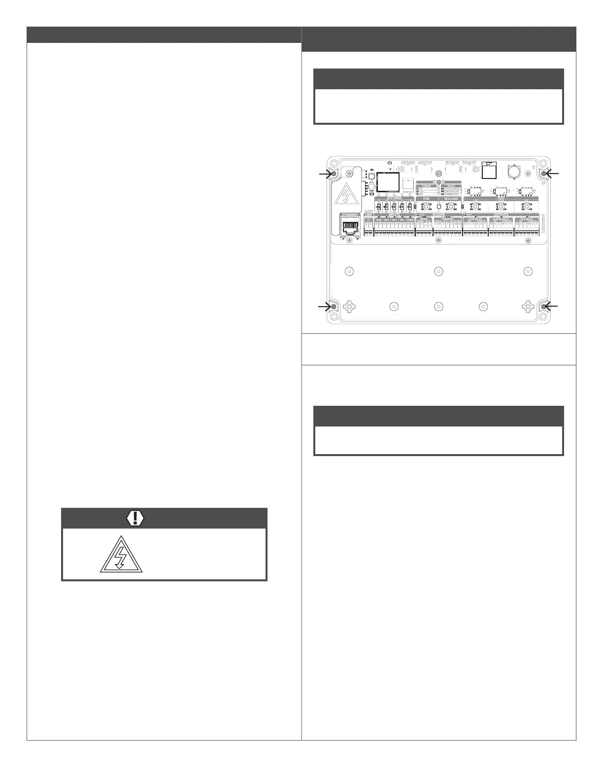
Mounting the CTE
Follow these steps to permanently attach the CTE enclosure.
NOTICE
For Bluetooth connectivity at the door, the CTE needs to be
mounted within Bluetooth connectivity range of the door.
Bluetooth radio is in the CTE.
1a ” (44 mm)
deep, located to match the mounting holes, shown below.
1b If the location does not adequately support the CTE,
mounting anchors should be used (not included).
1c Mount the CTE using appropriate #6 mounting hardware
(not included).
NOTICE
For security, mount the CTE in a location not accessible by
the public.