4
Connecting the CTE to Access Control Peripherals
Supported Peripherals
• One (1) UL listed RS-485 credential reader.
• Three output interfaces (See table in Power on page 5 for
details):
- Lock
- Alarm
- Auxiliary (AUX)
• Five optional inputs:
- REN: request to enter
- REX: request to exit
- DPS: door position sensor
- REL: remote release
- TAMP: reader tamper (Not required for RS-485 reader)
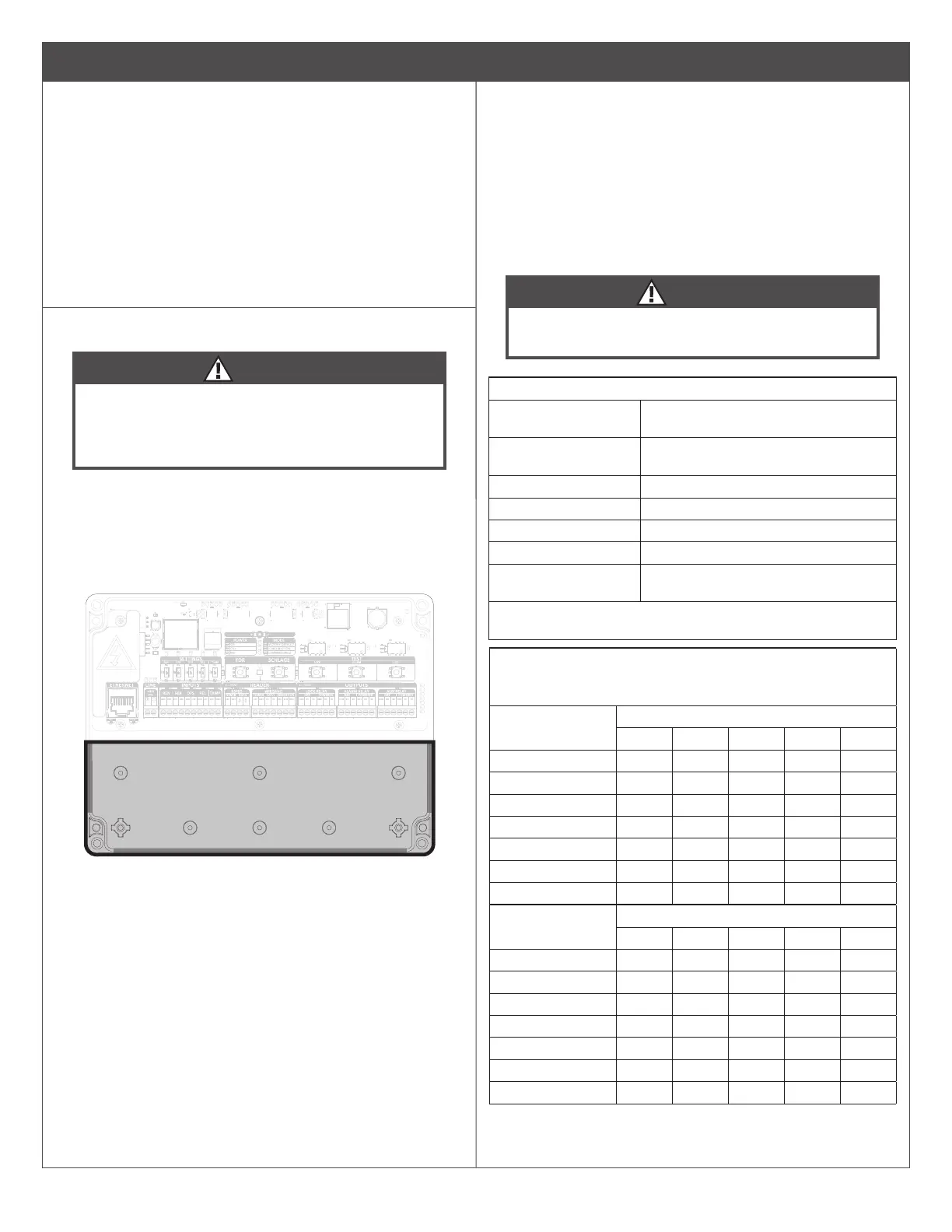
A Drill hole(s) in the CTE enclosure to accommodate the
size and number of entry/exit connectors to be used.
CAUTION
To avoid damage to electronics inside the enclosure
when drilling, use light pressure so that the bit does not
penetrate very far when it breaks through the enclosure.
Do not remove electronics!
NEMA Gland Note
Select an appropriately rated NEMA gland to maintain the enclosure’s
NEMA rating. Size the NEMA gland appropriately per application
wiring requirements. To achieve an appropriate seal on applications
requiring CAT5e/6 cable, run the cable through the NEMA gland
before crimping the RJ-45 connector
Drill enclosure only in shaded areas above (the back of the enclosure
and the left, right, and bottom walls). Do not drill near the electronics.
B
Wiring methods should be in accordance with the National Electric
Code (ANSI/NFPA70), local electric codes and the authorities having
jurisdiction. Cabling and wire must be UL listed and recognized wire
suitable for the application. Use only stranded, multi-conductor
wire without splices.
• Refer to Cable/Wire Table 1 - Typical Installation for wire
•
CAUTION
Do not coil wires inside the enclosure. Do not place
excess wire length near electronics!
Cable/Wire Table 1 - Typical Installation (shielded cable)
DC power input Belden 8760 18 2 conductor (100
feet/30.5 meters)
Door position switch Belden 8760 18 2 conductor shielded
(500 ft/152.5m)
Request to exit Belden 8760 18* (up to 500 ft/152.5m)
Lock relay output Belden 8760 18* (up to 500 ft/152.5m)
Auxiliary relay output Belden 8760 18* (up to 500 ft/152.5m)
Alarm relay output Belden 8760 18* (up to 500 ft/152.5m)
Schlage RS-485
credential reader
Alpha 1294C 22 4 conductor shielded (up
to 500 ft/152.5m)
* Typical application. See Cable/Wire Table 2 for load/power wire
runs.
Cable/Wire Table 2 - Wire Gauge Requirements
Use the CTE cable entry/exit connectors provided or that comply
with local electrical codes (e.g. conduit, etc.)
Total length to
device
Output Load current @ 12VDC
100mA 250mA 500mA 1A 2A
20 ft (6.1 m) 22 22 22 18 18
50 ft (15.2 m) 22 22 22 18 18
100 ft (30.5 m) 22 22 18 18 -
200 ft (61 m) 22 18 18 - -
300 ft (91.5 m 22 18 16 - -
400 ft (122 m) 18 18 - - -
500 ft (152.5 m) 18 16 - - -
Total length to
device
Output Load current @ 24VDC
100mA 250mA 500mA 1A 2A
20 ft (6.1 m) 22 22 22 22 22
50 ft (15.2 m) 22 22 22 22 18
100 ft (30.5 m) 22 22 18 18 18
200 ft (61 m) 22 22 18 18 -
300 ft (91.5 m 22 22 18 16 -
400 ft (122 m) 22 18 18 - -
500 ft (152.5 m) 22 16 16 - -