HandPunch 2000 Manual
15
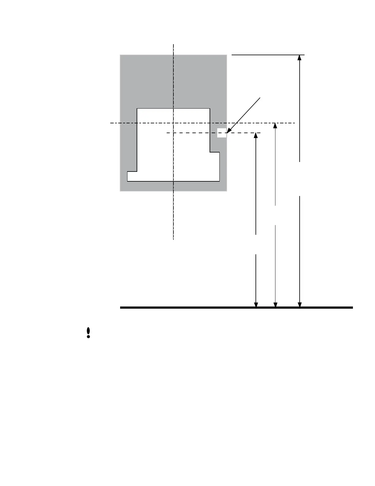
Wall Plate
Finished Floor
C
L HandPunch
SURFACE
CONDUIT
ENTRY POINT
C
L
42.5"
(108 cm)
42.75"
(108.6 cm)
50" Reference
(127 cm)
to Top of
Wall Plate
Figure 3-2: HandPunch Wire Routing Layout
Dust and debris surrounding the HandPunch can drastically affect the terminal’s
operation. It is important to ensure the HandPunch mounting location is free from dust
and debris.
1. Remove the HandPunch from its carton.
2. Align the sleeves of the back plate with the pins of the wall plate and slide the
HandPunch to the left as shown in “Figure 3-3”.
Attaching the
HandPunch
 Loading...