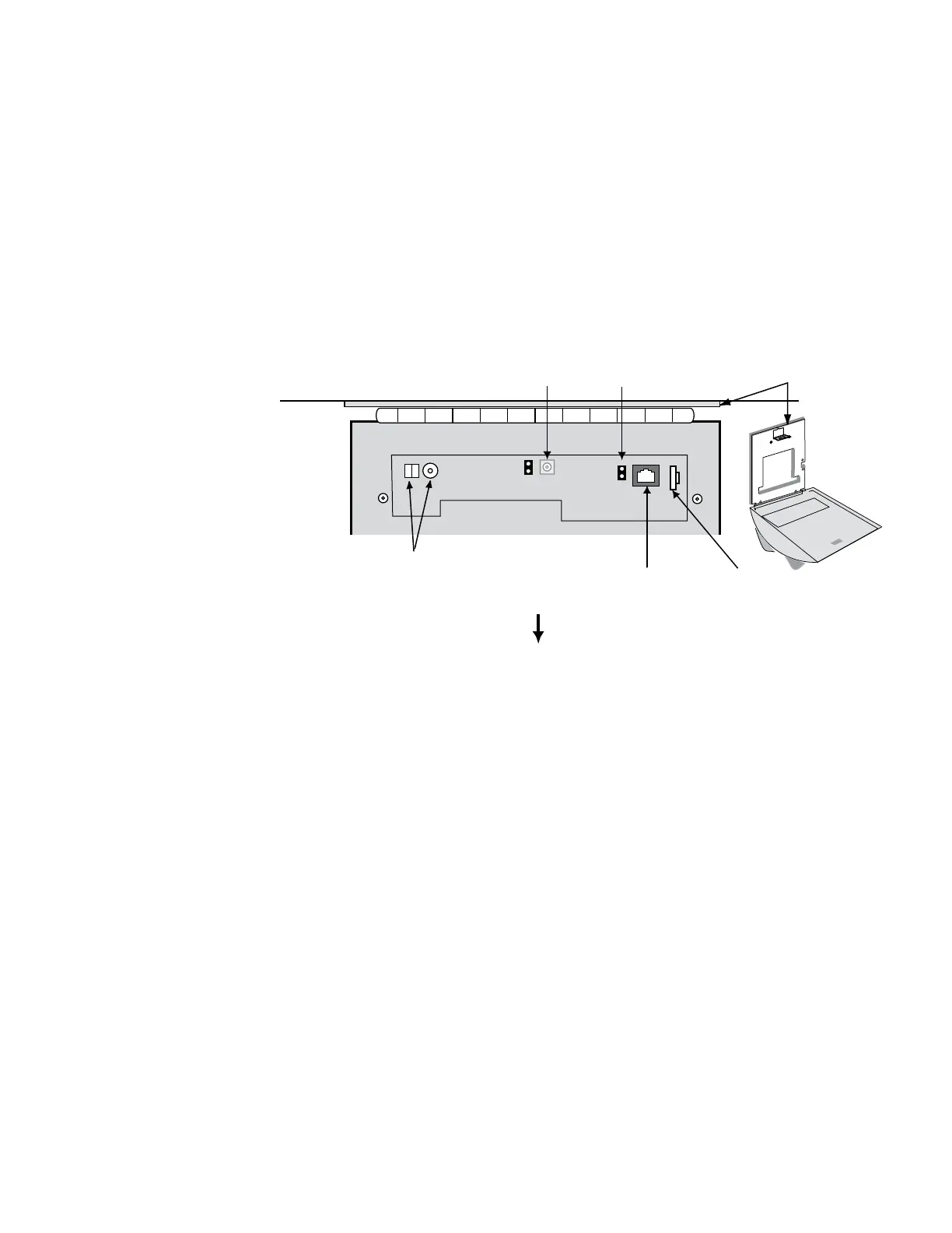
Wiring Connections
Once the HandPunch is attached to the wall plate the wiring connections to the
HandPunch can be made (see Figure 4-1).
WALL
Serial RS-232
Optional Modem
Wall Plate
Top of
Terminal
Top of HandPunch
Power
Connectors
J7 Battery
Jumper
Reset
Switch
Figure 4-1: Board Layout
Table 2 on page page 18 provides the pinouts for the RS-232 Serial Host Computer
Connection.
Figure 4-2 on page page 18 provides a diagram of the RS-232 Connector.
Figure 4-3 on page page 19 provides a Serial Connection diagram
Figure 4-4 on page page 19 provides a Host PC to HandPunch Modem Network wiring
diagram (Modem wiring is a HandPunch option).
Wiring
Examples
 Loading...