Appendix C - Mechanical Installation
48
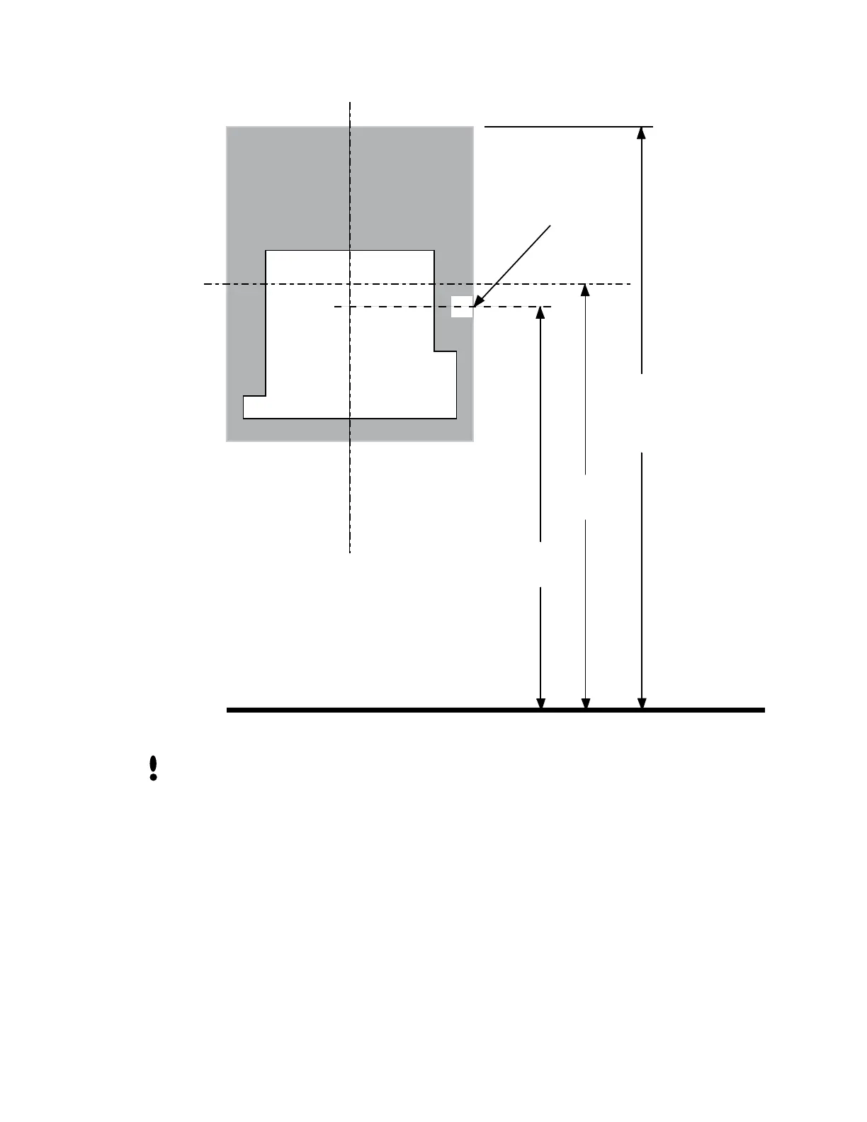
Wall Plate
Finished Floor
C
L HandPunch
SURFACE
CONDUIT
ENTRY POINT
C
L
42.5"
(108 cm)
42.75"
(108.6 cm)
50" Reference
(127 cm)
to Top of
Wall Plate
Figure 12-2: HandPunch Wire Routing Layout
Dust and debris surrounding the HandPunch can drastically affect the terminal’s
operation. It is important to ensure the HandPunch mounting location is free from dust
and debris.
1. Loosen the three bottom mounting screws until there is approximately 1/8 inch (3
mm) clearance between the screw head and the wall plate.
2. Remove the HandPunch from its carton.
3. At the base of the HandPunch is a piano hinge with three keyhole shaped slots that
correspond with the three lower mounting screws. Align and hang the HandPunch
from the three lower mounting screws (see Figure 12-3 on page page 49).
4. Tighten all three lower mounting screws.
5. The HandPunch is now ready for its wiring connections.
Attaching the
HandPunch
 Loading...