Copyright © 2021 Axxiom Manufacturing, Inc.
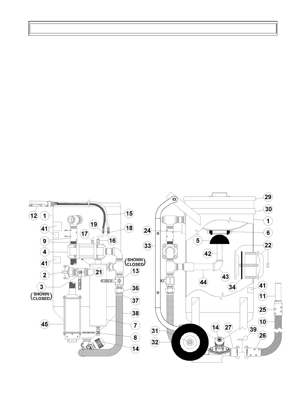
See Figure 5.1 below or Figure 9.2(a) to help understand the general operation of a MV3 abrasive
blaster. Do not attempt to operate the abrasive blaster before reading all sections of this manual and
following all setup procedures. Read Sections 5.1 through 5.17 for a detailed explanation of all
components of the MV3 abrasive blaster.
The MV3 abrasive blaster is a depressurized system; meaning the blaster will pressurize only when the
ComboValve® is opened by pressing the deadman lever (#12).
Compressed air enters the blast system when the air inlet ball valve (#3) is opened. Air flows through
the moisture separator (#7) and into the supply side of ComboValve (#4). Air is supplied to the
deadman valve (#12) from the ComboValve. When the deadman lever (#12) is pressed down signal air
will flow back to open the ComboValve. When the ComboValve opens air will flow into the blast
vessel internal piping. The air flow pushes the popup (#5) against the gasket (#6) to seal the abrasive
inlet and allow the air flow to pressurize the blast vessel (#1) and the blaster piping (#13).
Blasting starts when the deadman lever (#12) is pressed down. Compressed air will flow from the
ComboValve (#4) to the blast hose (#10). The choke ball valve (#13) must be open during the blast
operation. Abrasive will flow through the MV3 Valve (#14) and fall into the blast air stream. The
abrasive flow can be increased or decreased by turning the knob on top of the MV3 Valve (#14).
Because of the length of the blast hose, it will take a few seconds to see changes in abrasive flow.
Blasting stops when the deadman lever (#12) is released. This will close the ComboValve (#4) and
depressurize the vessel at the same time. The compressed air in the abrasive blaster will exhaust
through the blowdown hose (#9) and through the VBS Suppression System (#45). The MV3 abrasive
blaster (#1) remains depressurized when the ComboValve (#4) is closed.
Figure 5.1 – MV3 Abrasive Blaster with pneumatic blast controls
5.0 MV3 Abrasive Blaster General Operation