Copyright © 2021 Axxiom Manufacturing, Inc.
6.1.6. Verify that all required personal protective equipment is available for each operator and
in good operating condition (safety glasses, safety shoes, ear plugs, gloves, airline filter,
respirator, & carbon monoxide monitor). Critical: Adhere to all local, state, and federal
regulations including, but not limited to, OSHA (Occupational Health and Safety
Administration). Pay close attention to requirements regarding breathing air quality.
When an oil-lubricated air compressor is used, additional requirements for a high
temperature alarm and/or a carbon monoxide monitor become necessary. See Sections
3.9 and 3.10.
Failure to use personal protective equipment could result in serious injury or death.
6.1.7. Hose clamp the deadman (#12) to the blast hose assembly in a comfortable position
behind the nozzle holder (#25).
6.1.8. Wire tie the twinline hose (#15) or electric deadman extension cords to the blast hose
assembly (#10).
6.1.9. Screw nozzle (#11) into the nozzle holder (#25) at end of the blast hose assembly (#10).
6.1.10. Connect the blast hose coupling (#26) to the threaded coupling (#27) on the abrasive
metering valve (#14). Then install safety pins (#39) and a hose whip check (#40) to
protect against accidental disconnections during operation. See Sections 5.12, and 8.7.
Failure to install safety pins on all blast hose couplings can result in hose disconnects
and could result in serious injury or death. See Sections 5.12 and 8.7.
6.1.11. Connect the twinline hose quick disconnects (#18 & #19) or the electric deadman
extension cord to the mating disconnect(s) (#16 & #17) on the abrasive blaster piping.
6.1.12. Close the air inlet ball valve (#3).
6.1.13. Connect a 150psi rated (minimum) air supply hose to the air inlet crowfoot (#2) and
install safety pins (#39) and a hose whip check (#40) to protect against accidental
disconnections during operation. See Sections 5.12 and 8.7.
Failure to install safety pins on all air hose couplings can result in hose disconnects and
could result in serious injury or death. See Sections 5.12 and 8.7.
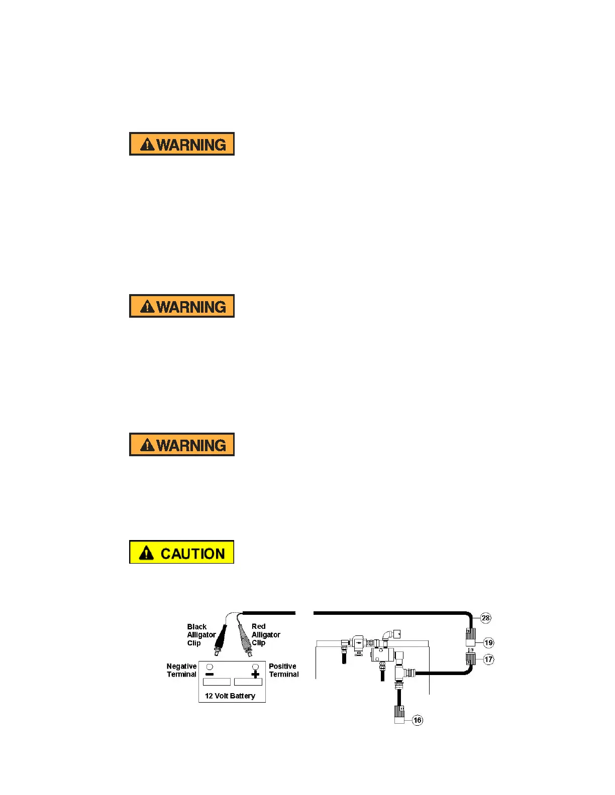
6.1.14. The following steps apply only to abrasive blasters with electric systems. Connect the
electric power cord (#28) to the blaster junction tee connector (#17).
6.1.15. Connect the electric power cord alligator clips (#28) to the air compressor battery
terminals or to another 12Vdc power source. See Figure 6.1.
Electric shock hazard. Abrasive blasters with electric deadman blast control systems
must operate on low voltage supply (12-24 volts). To minimize shock hazard only use
low voltage sources and use caution when connecting the power to the abrasive blaster.
See Section 3.7.
Figure 6.1 – Electric power connection