88
OMMON INDUSTRIAL AIR COMPRESSOR
DRY AND CLEAN
INDUSTRIAL AIR
DRY AND PRE-FILTERED
INDUSTRIAL AIR
Air quality in compliance with the ISO 8573.1 STANDARD - Class 1.4.1
COMMENTS: For other configurations consult with the factory.
All other components perform the maintenance as explained in the
specific instruction manual. The installation displayed is merely illustrative.
Note: The customer is responsible for all installation and accessories.
8
9
7
4
4
5. Electrical Hookups
Consult with a specialized technician to evaluate the overall conditions of the electrical network and select adequate protective
power supply devices.
The power supply cables must be dimensioned in consideration of the SRS - Air Dryer power consumption and the distance from the elec-
trical power source (See Table 6.1).
The power distribution shall not display a voltage variation range over ± 10%.
The voltage supplied by the startup peak shall not be over 10%.
For safety reasons the SRS - Air Dryer chassis must be adequately connected to an electrical installation ground wire cable.
In figure 9.2 until 9.10, are displayed the electrical diagrams which contain the electrical schematic drawings for each model of the SRS - Air
Dryer Line.
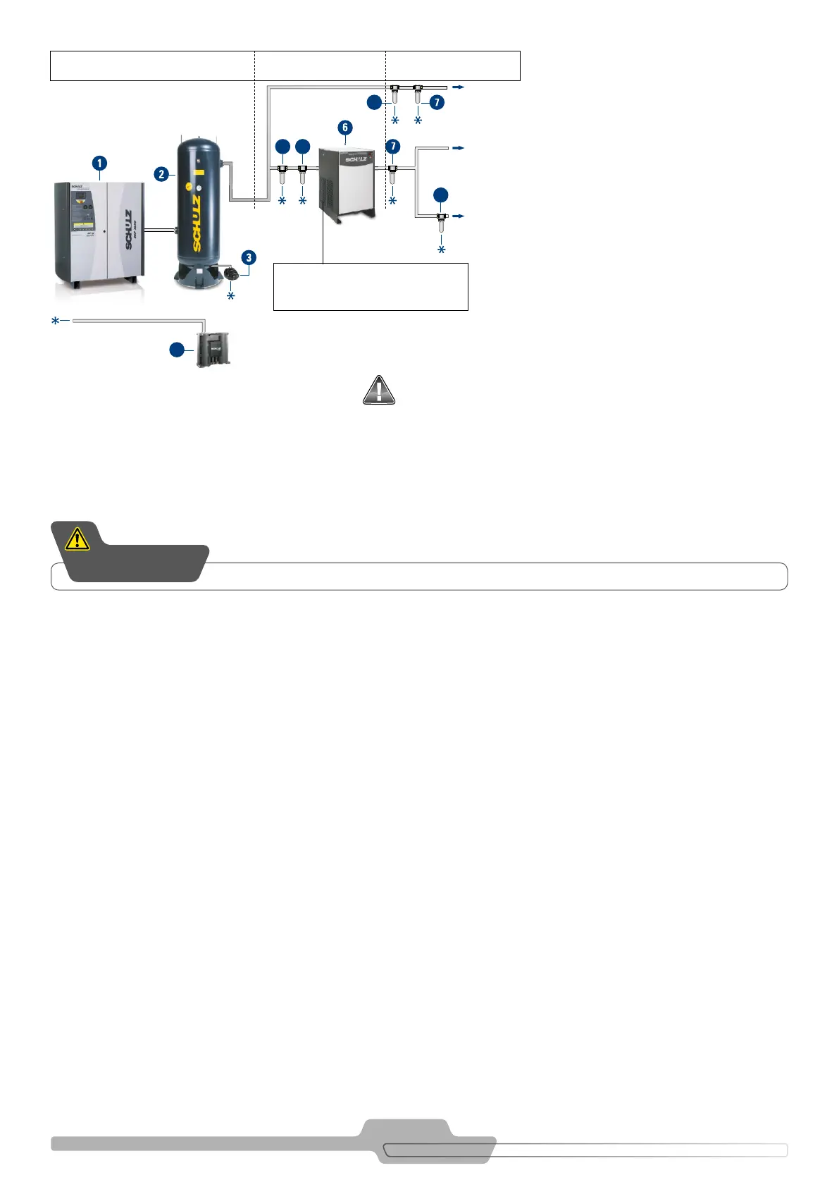
FIGURE 9.1 – A TYPICAL INSTALLATION OF A SCREW COMPRESSOR INCLUDING COMPRESSED AIR TREATMENT PERIPHERICALS
Classe 1.7.1
Line
Classe 1.7.1
The dryer must be installed in
a dry and well-ventilated location.
1. SCREW COMPRESSOR
2. CONDENSED SEPARATOR (RESERVOIR)
3. ELECTRONIC DRAIN PS16
4. COALESCENT AFTER-FILTER - CLASS 1.7.1
5. COALESCENT AFTER-FILTER - CLASS 1.7.1
6. REFRIGERATION AIR DRYER
7. COALESCENT AFTER-FILTER - CLASS 1.7.1
8. ACTIVATED CARBON FILTER
9. LIQUID SEPARATOR (OIL / WATER)
The local standards and regulations for Low Voltage Electrical Installations must be complied with.
ATTENTION