Assembly
22
02.00 | GWB | Assembly and Operating Manual | en | 389122
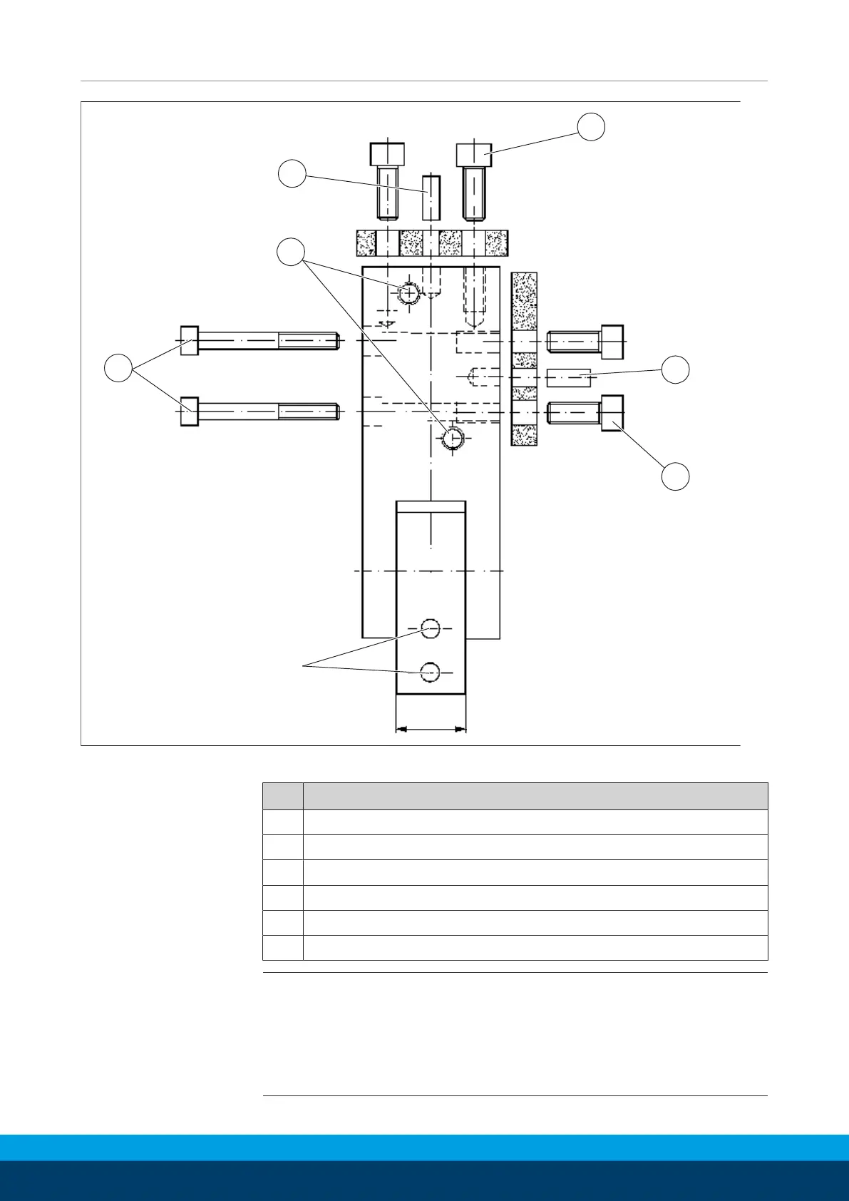
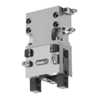
Mounting and centering the GWB 100
Item GWB100
1 4x DIN EN ISO 8734 - Ø 8m6 x 20
2 M5 for hose connection
3 4x DIN EN ISO 4762 - M8 x 65
4 4x M10 screw - 15 mm depth of engagement
5 2x DIN EN ISO 8734 - Ø 8m6 x 20
6 4x M10 screw - 15 mm depth of engagement
NOTE
• When mounting the module from the rear or side, use the
fixing bores provided.
• Fasten the module using the fixing bores provided.
• Fasten the top jaws using the fixing bores provided.


 To Next Page