Montage- und Betriebsanleitung für
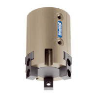
Schwenkkopf Type PSK 16
Assembly and Operating Manual for
Swivel Head Type PSK 16
5
3. Lieferumfang
– Kompakt-Schwenkkopf PSK 16
mit 1 Leiterplatte mit Stecker
(ohne Adapterplatte und Näherungsschalter)
– Beipack:
– 6 O-Ringe Ø 4 x 1.5
– 4 O-Ringe Ø 3 x 1
– 4 O-Ringe Ø 4 x 1
– 6 Gewindestifte M 5 x 5
4. Technische Daten
(siehe Katalog)
HINWEIS:
Bitte prüfen Sie, ob Ihr Einsatzfall anhand des Berechnungs-
programms »Auswahlsystem für SCHUNK-Schwenkeinheiten«
geprüft wurde. Falls nicht, kann keine Gewährleistung übernom-
men werden.
– Der vom Schwenkkopf ausgehende Luftschall ist ≤ 70 dB (A)
5. Montage
ACHTUNG!
Bei der Montage des Schwenkkopfes muss die
Energieversorgung abgeschaltet sein. Beachten Sie
auch die Sicherheitshinweise auf den Seiten 3 und 4.
5.1 Befestigung des Schwenkkopfes
Befestigen Sie den Schwenkkopf mit den 4 Gewinden M 5 oder
durch die Kernlochbohrungen mit Schrauben M 4.
Die Positionierung wird über 2 Passbohrungen Ø 5
H7
(Zylinder-
stift Ø 5m6) an der Anschraubfläche erreicht.
3. Scope of delivery
– Swivel Head PSK 16
with 1 wired circuit board with plug
(without adaptor plate and proximity switches)
– Little plastic bag:
– 6 O-rings Ø 4 x 1.5
– 4 O-rings Ø 3 x 1
– 4 O-rings Ø 4 x 1
– 6 Set screws M 5 x 5
4. Technical data
(see catalog)
NOTE:
Before operation, please check if your case of application was
calculated by means of the “SCHUNK calculation program selec-
tion system for Swivel Units”. If not, there will be no guarantee on
this application.
– The airborne noise emitted by the swivel head is ≤ 70 dB (A)
5. Mounting
CAUTION!
Before mounting the swivel head switch off the
power source. Please observe the safety instructions
on page 3 and 4.
5.1 Fastening of the swivel head
Fasten the swivel head with the 4 threads M5 or via the core
removing holes with screws M4.
Positioning is done via 2 fitting bores Ø 5
H7
(cyl. pin Ø 5m6) at
the screw plate.
5.2 Befestigung am Schwenkkörper
Befestigen Sie die Adapterplatten mit den 4 Gewinden M 4 oder
durch die Kernlochbohrung mit Schrauben M 3. Positionieren Sie
die Adapterplatten mit den 2 Passbohrungen Ø 4
H7
(Zylinderstift
Ø 4m6) am Schwenkkörper.
5.2 Fastening of the swivel body
Fasten the adaptor plates with 4 threads M4 or via the core
removing holes with screws M3. Positioning of the adaptor plates
is done via the 2 fitting bores Ø 4
H7
(Ø 4m6) at the swivel body.
Gewinde M 5 (4 x)
Threads M 5 (4 x)
Passbohrung Ø 5
H7
(2 x)
Fitting bore Ø 5
H7
(2 x)
Schwenkkörper
Swivel body
Gewinde M 5 (4 x)
thread M 5 (4 x)
Passbohrung Ø 5
H7
(2 x)
fitting bore Ø 5
H7
(2 x)