SP-MSTR-AC-11A
STR Manual
RD: NOV, 2003
RL: 11
KH
5. SYSTEMS INCORPORATING 90
O
BENDS AND 180
O
ELBOWS
Page 4
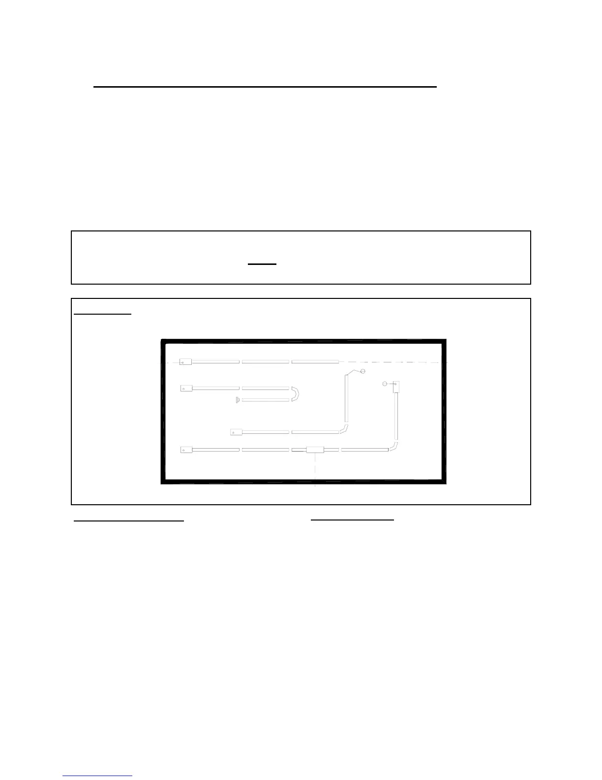
The STR Series radiant tube heater can be
installed in configurations as illustrated in
FIG: 2 (below) with a maximum of two 90
o
or one 180
o
elbow per heater. The use of
radiant elbows reduces the total maximum
vent allowable. See SECTION 9 (page 11):
Flue Venting.
Both the 90
o
and 180
o
elbows are shipped as
a kit with two end-plate hangers to close off
the reflector ends each side of the elbow (s).
The reflector must be secured with four
screws to each of the end-plate-hangers.
SEE FIG: 3 (PAGE 5) and FIG: 6 (PAGE 6).
FIGURE 2 SYSTEM CONFIGURATIONS
System Configuration
1 Straight line
2 “U” tube with 180-degree elbow kit
3 “L” tube with 90-degree elbow kit
4 Twinned tubes into common TEE flue
vent
Venting Options
A Flue vent through wall 4”
B Flue vent through wall or roof 6”
C Flue vent through roof
D Flue vent into building, exhaust fan
interlocked with heater
E Combustion air intake from outside
through wall
F Combustion air intake from outside
through roof
G Combustion air intake from inside
building
IMPORTANT: On STR 60 and 45 models, a minimum of 10’ of straight
radiant tube must
be connected to the burner before any
elbow.
A
F
C
G
D
E
B
1
2
3
4
G
G