SEL-487V Data Sheet Schweitzer Engineering Laboratories, Inc.
14
oscillographic display of the battery voltage. Monitor the
substation battery voltage drops during trip, close, and
other control operations.
Breaker Monitor Feature Allows
for Wear-Based Breaker Mainte-
nance Scheduling
Circuit breakers experience mechanical and electrical
wear at each operation. Effective scheduling of breaker
maintenance takes into account the manufacturer’s
published data of contact wear versus interruption levels
and operation count. The SEL-487V breaker monitor
feature compares the breaker manufacturer’s published
data to the integrated actual interrupted current and
number of operations.
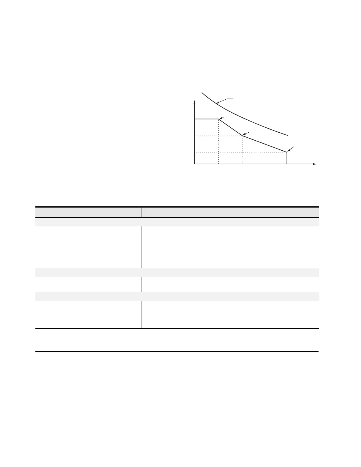
➤ Every time the breaker trips, the relay integrates
interrupted current. When the result of this integra-
tion exceeds the threshold set by the breaker wear
curve (Figure 15), the bay can alarm via an output
contact or the optional front-panel display. With
this information, you can schedule breaker mainte-
nance in a timely, economical fashion.
➤ Monitor last an average mechanical and electrical
interruption time per pole. You can easily deter-
mine if operating time is increasing beyond reason-
able tolerance to schedule proactive breaker
maintenance. You can activate an alarm point if
operation time goes beyond a preset value.
➤ Breaker motor run time and breaker inactivity are
also recorded for each breaker operation.
Figure 15 Breaker Contact Wear Curve and Settings
Automation
Flexible Control Logic and
Integration Features
SEL-487V control logic:
➤ Replaces traditional panel control switches
➤ Eliminates RTU-to-bay wiring
➤ Replaces traditional latching relays
➤ Replaces traditional indicating panel lights
➤ Performs real-time control using synchrophasor data
Eliminate traditional panel control switches with 32 local
control points. Set, clear, or pulse local control points
with the front-panel pushbuttons and display. Program
the local control points to implement your control
scheme via SEL
OGIC control equations. The local control
points provide functions such as trip testing,
enabling/disabling reclosing, and tripping/closing circuit
breakers.
kA Interrupted
(Set Point 1)
(Set Point 2)
(Set Point 3)
Breaker Manufacturer's
Maintenance Curve
Close to Open Operations
Table 5 Metering Capabilities
Capabilities Description
Instantaneous Quantities
Voltages
VA, B, C (Y), VA, B, C (Z), V, 3V0, V1, 3V2
0–300 V with phase quantities for each of the six voltage sources available as a sepa-
rate quantity.
Currents
I
A,B,C
(W), I
A,B,C
(X)
I
A
L, I
B
L, I
C
L (combined currents)
IGL, I1L, 3I2L (combined currents)
Phase quantities for each of the two current sources available as a separate quantity or
combined as line quantities.
Power/Energy Metering Quantities
MW, MWh, MVAR, MVARh, MVA, PF,
single-phase, and three-phase
Available for each input set and as combined quantities for the line.
Demand/Peak Metering
I
A,B,C
, 3I2, 3I0 Thermal or rolling interval demand and peak demand.
MW, MVAR, MVA, single-phase Thermal or rolling interval demand and peak demand.
MW, MVAR, MVA, three-phase Thermal or rolling interval demand and peak demand.