SEL-787-2, -3, -4 Data Sheet Schweitzer Engineering Laboratories, Inc.
10
➤
Two neutral instantaneous overcurrent (50N) ele-
ments that operate on the neutral current associated
with the neutral channel (MOT dependent).
Time-Overcurrent Elements
The time-overcurrent elements support the IEC and U.S.
(IEEE) time-overcurrent characteristics shown in
Table 4.
Electromechanical disk reset capabilities are provided
for all time-overcurrent elements. The following time-
overcurrent elements are available in the SEL-787.
➤ One maximum phase time-overcurrent (51P) element
per winding that operates on the maximum of the cor-
responding winding phase currents.
➤ Three per-phase (A-, B-, and C-phase) time-overcur-
rent (51P) elements, one element per phase, that oper-
ate on the corresponding phase current of Winding 3
(only available on models with Winding 3).
➤ One negative-sequence time-overcurrent (51Q) ele-
ment per winding that operates on the calculated neg-
ative-sequence current.
➤ One residual time-overcurrent (51G) element per
winding that operates on the calculated residual (3I0)
current.
➤ One neutral time-overcurrent (51N) element that
operates on the neutral current associated with the
neutral channel (MOT dependent).
Combined Time-Overcurrent Elements
The combined time-overcurrent elements can be used for
transformers connected to a ring-bus or breaker and one-
half systems. The SEL-787-4X/2E/3S models allow you
to combine Winding 1 and Winding 2 and/or Winding 3
and Winding 4 currents. The following combined time-
overcurrent elements are available:
➤ Two phase time-overcurrent (51P) elements, one each
for combined Windings 1 and 2 and Windings 3
and 4, that operate on the maximum of the corre-
sponding combined phase currents.
➤ Two zero-sequence time-overcurrent (51G) elements,
one each for combined Windings 1 and 2 and
Windings 3 and 4, that operate on the calculated zero-
sequence current of the corresponding combined cur-
rents.
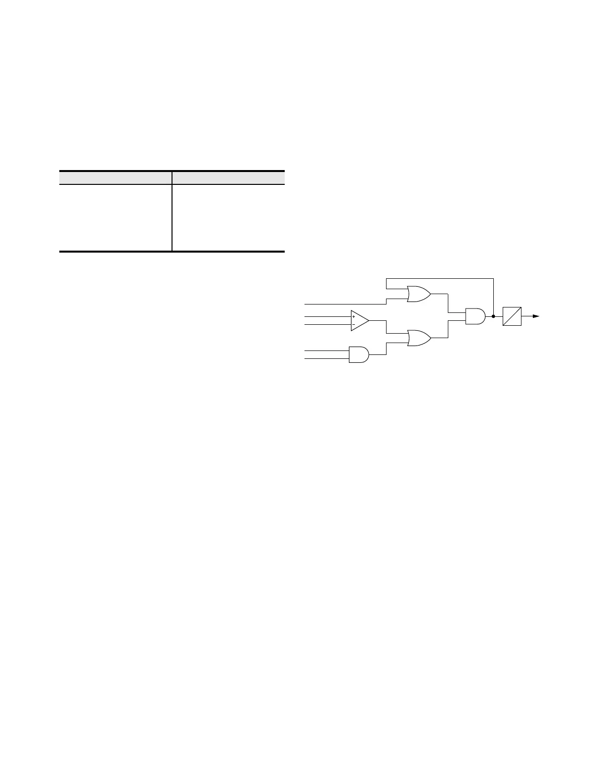
Breaker Failure Protection
The SEL-787 offers breaker failure protection for as
many as four three-pole breakers. Use breaker failure
detection to issue retrip commands to the failed breaker
or to trip adjacent breakers using the relays contact out-
put logic or communications-based tripping schemes.
Breaker failure is initiated by the breaker failure initiate
(BFI) SEL
OGIC input. The BFI input is typically driven
by local and remote open/trip commands to the breaker.
Once the BFI input is received, the breaker failure
element monitors positive- and negative-sequence
current magnitudes and the breaker auxiliary contacts to
determine when to initiate the breaker failure delay timer.
If current or breaker auxiliary contact status does not
indicate an open breaker condition within the time set by
the breaker failure delay timer, the element issues a
breaker failure trip output.
Figure 6 Breaker Failure Protection
Volts/Hertz Protection
Overexcitation occurs when the magnetic core of a
power apparatus becomes saturated. When saturation
occurs, stray flux is induced in nonlaminated compo-
nents, which can result in overheating. By ordering the
voltage option for the SEL-787, you can add a volts/hertz
element to detect overexcitation. An SEL-787 with
optional voltage inputs provides a sensitive definite-time
delayed element, plus a tripping element with a compos-
ite operating time.
For example, the relay calculates the transformer
volts/hertz as a percentage of nominal, based on
measured values and the nominal voltage and frequency
settings. The relay starts a timer when the system voltage
causes an excursion that exceeds the volts/hertz
overexcitation setting. If the condition remains for the set
time delay, the relay asserts and typically provides an
alarm function. The element is supervised by the
SEL
OGIC torque control equation, which enables or
disables the element as required by the application.
Use the SEL-5806 Curve Designer Software to set the
user-defined curve (see Figure 7). For tripping, the relay
provides a time-integrating element with a settable
operating characteristic. You can set the relay element to
operate as an inverse-time element; a user-defined curve
element; a composite element with an inverse-time
Table 4 Inverse-Time Overcurrent Curves
U.S. (IEEE) IEC
Moderately Inverse Standard Inverse
Inverse Very Inverse
Very Inverse Extremely Inverse
Extremely Inverse Long-Time Inverse
Short-Time Inverse Short-Time Inverse
BFD
0
BFT
BFI
|I1| + |I2|
0.02 • INOM
52A
52ABF