SEL-787-2, -3, -4 Data Sheet Schweitzer Engineering Laboratories, Inc.
12
Directional Power Element
Protection
The SEL-787 with optional voltage inputs provides two
directional power elements for detecting real (WATTS)
or reactive (VARS) directional power flow levels for the
transformer winding(s) associated with the three-phase
voltage input. Each directional power element has a
definite-time delay setting.
RTD Thermal Protection
When the SEL-787 is equipped with either an optional
10 RTD input expansion card or an external SEL-2600
RTD Module with as many as 12 RTD inputs, you can
program as many as 12 thermal elements in the relay for
two levels of thermal protection per element. Each RTD
input provides an alarm and trip thermal pickup setting in
degrees Celsius, open and shorted RTD detection, and is
compatible with the following three-wire RTD types:
➤ PT100 (100 platinum)
➤ NI100 (100 nickel)
➤ NI120 (120 nickel)
➤ CU10 (10 copper)
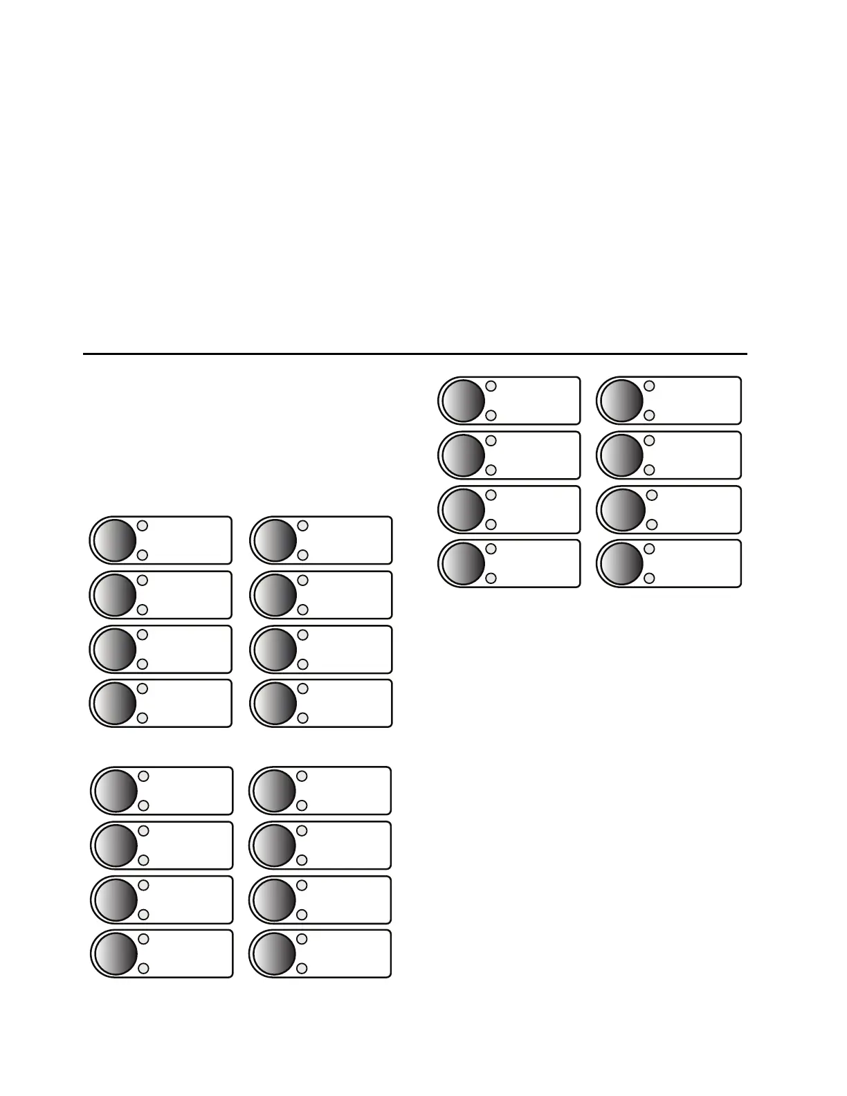
Operator Controls
Operator controls eliminate traditional panel control
switches. Eight conveniently sized operator controls,
each with two programmable tricolor LEDs, are located
on the relay front panel (see Figure 8, Figure 9, and
Figure 10). You can set the SER to track operator con-
trols. Use SEL
OGIC control equations to change operator
control functions. Use configurable labels to change all
of the text shown in Figure 8, Figure 9, and Figure 10.
Figure 8 Operator Controls (787-4X Model)
Figure 9 Operator Controls (787-3E/3S Models)
Figure 10 Operator Controls (787-2E/21/2X Models)
The following operator control descriptions are for
factory-set logic.
LOCK: The LOCK operator control blocks selected
functions. Press it for at least three seconds to engage or
disengage the lock function. When the LOCK pushbutton
is engaged, the CLOSE operator control is blocked.
BRKRn: Each of the BRKRn (n = 1, 2, 3, or 4) pushbuttons
allows you to select the breaker on which a close or trip
control operation is to be performed. Only one breaker
can be selected at any given time. Breaker select status
for a given breaker is indicated by the upper pushbutton
LED. The lower pushbutton LED indicates the
CLOSED/OPEN (RED/GREEN, respectively) status of
the corresponding breaker.
CLOSE and TRIP: Use the CLOSE and TRIP operator controls
to close and open the circuit breaker. You can program
these controls with intentional time delays to support
operational requirements for breaker-mounted relays.
This allows you to press the CLOSE or TRIP pushbutton,
then move to an alternate location before the breaker
command is executed.
BRKR4
SELECTED
CLOSED/OPEN
BRKR1
BREAKER CLOSING
CLOSE
BREAKER OPENING
TRIP
AUX1
SELECTED
BRKR2
SELECTED
CLOSED/OPEN
BRKR3
SELECTED
CLOSED/OPEN
CLOSED/OPEN
ENABLED
LOCK
DISABLED
ENABLED
LOCK
DISABLED
SELECTED
CLOSED/OPEN
BRKR1
BRKR2
SELECTED
CLOSED/OPEN
BRKR3
SELECTED
CLOSED/OPEN
BREAKER CLOSING
CLOSE
BREAKER OPENING
TRIP
AUX1
AUX2
ENABLED
LOCK
DISABLED
SELECTED
CLOSED/OPEN
BRKR1
BRKR2
SELECTED
CLOSED/OPEN
SELECTED
CLOSED/OPEN
BREAKER CLOSING
CLOSE
BREAKER OPENING
TRIP
AUX1
AUX2
AUX3