DESIGN AND CON STRUC TION DE SCRIP TION
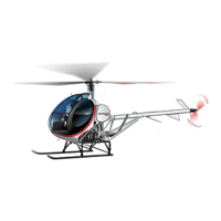
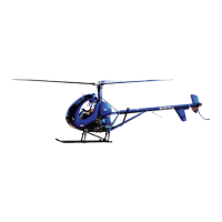
The 269C-1 helicopter has a three bladed, fully articulated single main rotor
system. A two bladed tail rotor is used for torque reaction and directional
control. Power is supplied by a Textron Lycoming Model HO-360-C1A
reciprocating engine (Original factory installation in S/N 0001-0138) or
HIO-360-G1A (Original factory installation in S/N 0139 & Subs.). The
engine power is transmitted through a belt drive transmission assembly to
the main transmission and tail rotor drive shaft. The belt drive assembly
incorporates an overrunning clutch to permit autorotation without driving
the belts or engine.
The fuselage with a central, tubular steel, open frame forms the
load-carrying structure for the helicopter. The center frame provides
attachments for and supports all helicopter components above the landing
gear, which is attached to the underside of the frame. The forward section
holds the pilot’s compartment; the cabin contains two seats, with the pilot’s
position on the right side. Seat cushions and backs are contoured for
personnel comfort. The seat support, to which the cushions are affixed,
provides an installation of maximum personnel safety as a result of the
impact-yielding capability. Seat belts and shoulder harnesses are provided
for the pilot and passenger positions.
An instrument panel is located forward of the seats at the helicopter
centerline. The panel includes flight and engine instruments in addition to
warning and caution lights and various switches and controls. Space
provisions exist for communication and navigation equipment. A 28 volt
accessory power plug is located below the left side of the instrument panel
on later serial number aircraft. Instrument consoles have a stowage
compartment (glove box) which can accommodate up to 20 lbs. additional
baggage.
The pilot’s position is on the right side of the cabin, with a cyclic control
stick and tail rotor pedals provided in front of the pilot’s seat. The pedals are
adjustable. A collective pitch control stick is provided to the left of the
pilot’s seat. The cyclic and collective control system is the mechanically
linked, solid type, using tubular push-pull rods. The tail rotor control system
utilizes cables and pulleys in one link of its otherwise solid system of tubular
push-pull rods. A cabin, mounted forward of the center frame, is formed by
the canopy, two cabin doors, a floor section and a seat structure. The cabin
encloses the pilot and passenger area and contains the flight controls, seats,
instrument panel and other furnishings. The canopy and door transparent
areas are of cast acrylic material. An airfoil which modifies the airflow
around the cabin, extends above and across the canopy upper windshield
section.
General
Pilot's Flight Manual
Reissued: 16 Jan 2019 1-5
SCHWEIZER
Model 269C-1 Helicopter
CSP book 2..indd 31 8/4/19 12:53 PM