111
Maintenance
SP 500 / 750-15 / 750-18 / 1000 / 1250 Operation Manual
The following steps are required for checking and
charging the accumulator:
1. Before you begin, you will need a charging kit
(Figure 32). Do not attempt to charge the accu-
mulators without one. Order the charge valve kit
assembly from Schwing America using part num-
ber 30355436.
2. You must use a high-pressure regulator with the
nitrogen bottle. If it was not supplied with the bot-
tle, order one before proceeding with this job.
3. Before beginning the charging procedure, stop
the engine, remove the key, and put a “Do Not
Operate” tag over the key switch. Put the key in
your pocket, so no one can start the engine.
4. Remove the valve protection cap and the valve
seal cap from the accumulator that you will charge
rst (Figure 33).
Accumulator
Valve Seal Cap
Valve Protection Cap
Valve Stem
O-ring
accum closeup
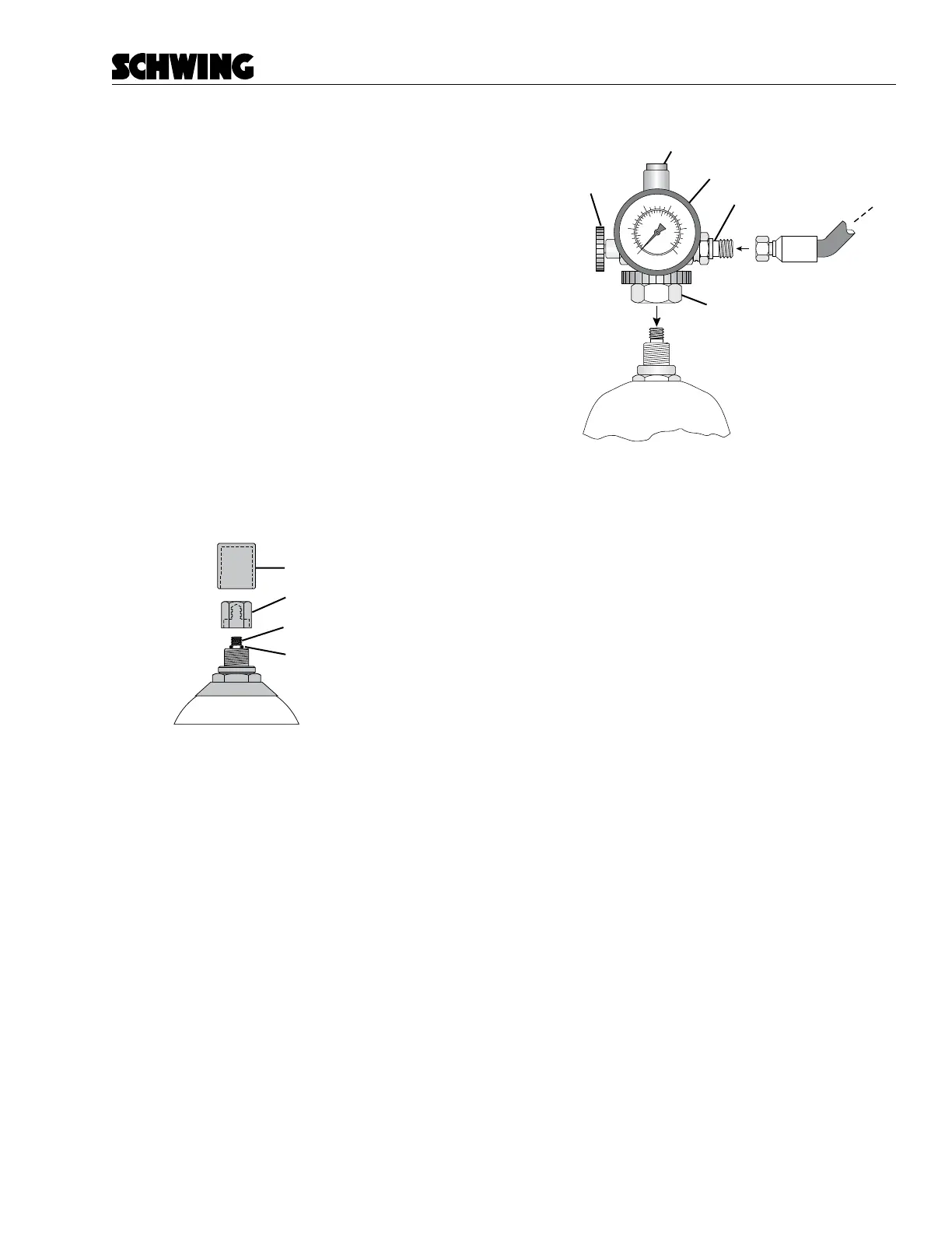
Figure 33
Accumulator protection cap
5. On the charge valve assembly (Figure 34), close
the bleed valve (turn it clockwise all the way in).
If a hose is connected to the charge valve stem,
disconnect the hose from the charge valve stem.
This step closes the charge valve stem to prevent
the gas pressure from escaping out of the hose.
It ensures that the initial pressure reading is ac-
curate.
500
0
50
200
250
100150
1000
1500
2000
3000
2500
3500
Swivel Nut
Accumulator
Bleed Valve
Push Button
Charge Valve Stem
Pressure Gauge
Figure 34
Charge valve assembly
6. Find the swivel nut on the charge valve assembly
(Figure 34). Screw the swivel nut onto the accu-
mulator gas valve. Tighten to 10–15 in./lb.
7. After the swivel nut is attached, depress the push
button on the top of the charge valve assembly
(Figure 34). This presses a pin into the accumula-
tor gas valve and opens it. Read the pressure on
the charge valve assembly pressure gauge. The
pressure should read 103 bar (1500 PSI).
• If pressure must be added, proceed to Step 8.
• If pressure is too high, skip to Step 12.
• If no adjustment is necessary, skip to Step 15.
8. Be sure that the nitrogen bottle supply valve is
rmly closed. Attach the high-pressure regulator
to the nitrogen bottle, then attach the hose to the
high-pressure regulator. Finally, attach the other
end of the hose to the charge valve stem on the
charge valve assembly (Figure 35).
9. Do not open the nitrogen bottle supply valve
yet. Turn the regulator adjustment handle on
the high-pressure regulator (Figure 35) counter
clockwise to its minimum setting (closed).