112
Maintenance
SP 500 / 750-15 / 750-18 / 1000 / 1250 Operation Manual
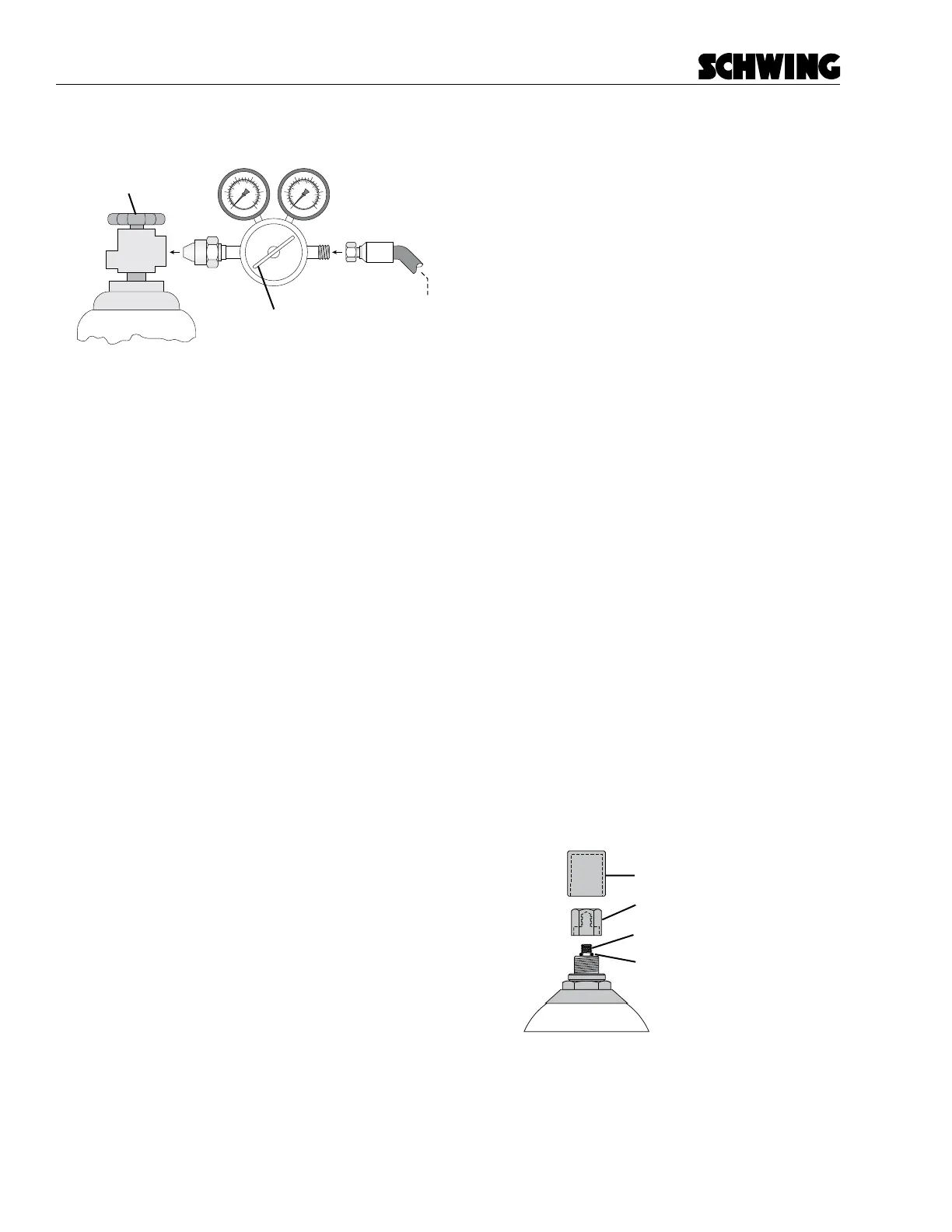
Regulator Adjustment
Handle
Nitrogen Bottle
Tank
Pressure
Regulated
Pressure
Nitrogen Supply Valve
bottleattach.eps
Figure 35
Nitrogen bottle and regulator
10. Slowly open the nitrogen bottle supply valve
(Figure 35). You will get a reading on the tank
pressure gauge side of the regulator. If there is
enough pressure in the nitrogen bottle to do the
job, proceed to the next step.
If there is not at least 1500PSI in the nitrogen bot-
tle (as shown on the regulator gauge at this time),
you will not be able to charge the accumulator
nitrogen to the 1500 PSI specication. If that is
the case, you will need a new bottle of nitrogen
before proceeding.
11. Adjust the regulator adjustment handle clockwise,
raising the regulated pressure. The accumulator
will begin to ll. Continue lling until the charge
valve assembly pressure gauge (Figure 35) reads
the desired pressure of 1500 PSI. Close the nitro-
gen bottle supply valve.
12. If you overcharge the nitrogen pressure, proceed
as follows:
• Close the nitrogen bottle supply valve.
• Depress the push button on the top of the
charge valve assembly.
• Slowly open the bleed valve on the charge kit.
Close the bleed valve when the correct pres-
sure is reached on the charge valve pressure
gauge.
Never let nitrogen out of the accumulator by
pressing the gas valve pin with a foreign object.
The high pressure may rupture the valve seal!
13. Let the nitrogen sit in the accumulator for 20 to
30 minutes. This allows the gas temperature to
stabilize. Depress the push button on top of the
charge valve assembly. Recheck the pressure on
the charge valve assembly pressure gauge.
14. Add or release nitrogen until the pressure is cor-
rect. Be sure that the bleed valve is closed before
adding pressure and that the nitrogen bottle sup-
ply valve is closed before releasing pressure.
15. When the correct pressure is reached, proceed
as follows:
• Close the nitrogen bottle supply valve.
• Open the charge valve assembly bleed valve.
This releases the pressure in the hose, charge
valve assembly, and regulator.
• While holding the charge valve assembly on
the accumulator, unscrew the charge valve
swivel nut.
• Remove the charge valve assembly.
• If you are nished with the charge valve as-
sembly, remove the hose and regulator.
16. Make a bubbly mixture from soap and water.
Spread the mixture around the accumulator gas
valve to check for gas leaks. Gas leaks will push
the bubbles away from the area of the leak. If you
nd a leak, replace the accumulator or have it
repaired by qualied personnel. Never repair an
accumulator yourself.
17. Replace the gas valve seal cap (tighten to 22 ft/
lb), and hand-tighten the valve protection cap
(Figure 36).
Accumulator
Valve Seal Cap
Valve Protection Cap
Valve Stem
O-ring
accum closeup
Figure 36
Accumulator protection cap