10.0 Table of Figures
|
49
10.0 Table of Figures
F
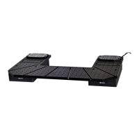
igure A: Motorised Moveable Base Plate, with key components
indicated ................................................................................................ 2
Figure B: Motorised stage mounting holes ............. Error! Bookmark not
defined.
Figure C: Mounting carriages. .............................................................. 14
Figure D: Platform locking mechanism. ................................................. 8
Figure E: Post and Platform locking collar ........................................... 10
Figure F: Rear panel of the 1U Rack mounted controller ..................... 15
Figure G: Basic electrical connections schematic ................................ 16
Figure H: Example system connection schematic ................................ 17
Figure I: Control cube user interface .................................................... 18
Figure J: PatchPad control device ....................................................... 20
Figure K: Joystick control device ......................................................... 22
Figure L: Top plate for use with the Scientifica SliceScope (1727) ....... 26
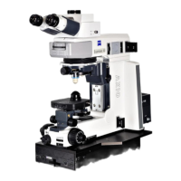
Figure M: Top plate for use with microscopes from Zeiss, Olympus and
Nikon (1726) ........................................................................................ 27
Figure N: Top plate for use with microscopes from Leica (1850) ......... 27
Figure O: Standard bath chamber platform .......................................... 28
Figure P: In vivo mounting platform ..................................................... 28