Do you have a question about the Scientifica MDU and is the answer not in the manual?
Important safety information related to general use of the Scientifica MDU.
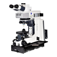
Describes the Scientifica Multiphoton Detection Unit (MDU) and its configurations.
Lists standard components included with the MDU for various configurations.
Instructions for attaching the above-stage MDU to the SliceScope microscope frame.
Describes the setup for the above-stage variant with a fixed objective.
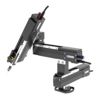
Describes the manual objective changer option for rapid objective interchange.
Details the MOC variant for automatic objective changes, typically for RMS-thread objectives.
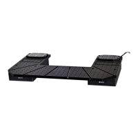
Describes the setup for the substage variant using a high-NA oil-immersion condenser.
Explains the use and installation of filter cubes for spectral response and two-channel detection.
Recommendations for transmission viewing, including Köhler illumination and dichroic mirror use.
Using transmitted IR laser radiation for imaging and generating reference images.
Details optics for imaging scanner mirrors onto the objective lens for efficiency and resolution.
Information on compatible control software and data acquisition.
Instructions for connecting the controller unit, including power and detector module cables.
Safety routine and steps for powering up the system for the first time.
Troubleshooting steps for a jammed dichroic mirror actuator, likely due to foreign bodies.
Steps to diagnose issues with the controller, including power supply and connections.
Diagnosing lack of high voltage, checking interlocks, connectivity, and cables.
Troubleshooting for a single detector not showing high voltage, checking interlocks and contacts.
Diagnosing lack of detector signal, checking data acquisition and connectivity.
Identifying causes of noise and offset at low detector gain, such as stray light.
Troubleshooting excessive noise at high gain, detector overload, or dark current.
Addressing variable noise and offset, often due to visible light entering the laser beam path.
Diagnosing smearing or trails in images, often due to scan speed exceeding detector bandwidth.
Troubleshooting excess noise in digitized signals, often caused by under-sampling.
Diagnosing low signal or high laser power requirements, checking spot intensity and aberrations.
Addressing image shading issues, often related to scanner occlusion or objective alignment.
Explains signal loss with depth due to scattering and reduced laser intensity.
Discusses limited field of view in images due to scanning too wide or deep.
Provides dimensional specifications for the above-stage variant with fixed objective.
Details specifications for the above-stage MOC variant, including objective compatibility.
Describes specifications for a four-channel system, useful for thick tissue slices.
Provides specifications for a combined MOC and substage variant system.
General procedure for removing and replacing detector modules for maintenance or repair.
Detailed steps for safely removing a detector module from the optical block.
Instructions for inspecting the optical block and PMT module before re-assembly.
| Category | Laboratory Equipment |
|---|---|
| Manufacturer | Scientifica |
| Axes | 3 |
| Resolution | 20 nm |
| Compatibility | Scientifica microscopes and third-party systems |
| Interface | USB |