Page 28 of 58
3.4.6 Re-assembly of the rear PMT module
Refer to the procedure in the appendix
9.3 Detector Module Replacement for replacing the rear PMT substage.
3.4.7 Installation of MOC variant onto the SliceScope
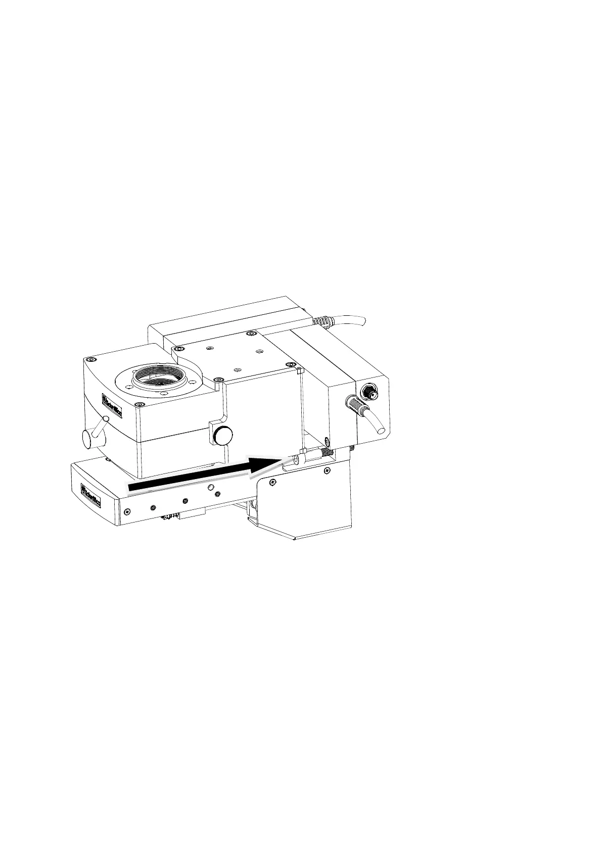
Figure Q: Side view of the optical block, bracket and MOC showing the side slot (under the rear detector module)
which accepts the M5 X 30 fixing bolts.
The whole assembly is fitted onto the SliceScope using two M4 X 30 hex cap-head bolts, and
alignment is provided by a groove and tongue arrangement as for the other variants of the system.
The two retaining bolts fit into holes in the bracket on either side of the assembly as shown in the
picture: access is restricted, so a long 4mm ball-nosed hex driver is required for installation.
Locate the two central M5 tapped holes in the SliceScope’s Z-axis focusing plate (marked as “A” in
Figure F).
Place one bolt into its slot, and hold it in place using the ball-ended hex driver whilst you offer the entire
assembly up to the Z-axis focus plate on the SliceScope. Drive the screw into the tapped hole in the
focus plate but do not tighten it fully.